EE109 – Spring 2023: Introduction to Embedded Systems
Lab 7
Rotary Encoders and Interrupts
Honor Statement
This is an individual assignment. The code you write, use for the demo and submit should be wholly your own and not produced by working in teams or using, in part or in whole, code written by someone else (found online, from a fellow student, acquaintance, etc.). You will be asked to verify this when you submit your code on Vocareum by signing your name in the honor.txt file on Vocareum. Penalties for violation include a 0 on the assignment and a potential further deduction or referral to Student Judicial Affairs.
Introduction
In this lab exercise you will learn how rotary encoders work and how the performance of the program can be improved by using interrupts rather than polling to monitor the inputs from the encoder.
The encoder will be used to control the incrementing and decrementing of a signed variable and the value of that variable will be displayed on the LCD shield. Turning the encoder in one direction increments the count, turning in the opposite direction decrements it. Each time the displayed value is a multiple of 8, a brief tone will be generated by a buzzer on the breadboard.
To see a short video demonstrating the operation of lab, click here.
For a copy of the Lab 7 grading sheet, click here.
Getting Started
Set up the Lab 7 assignment the same as has been done previously by creating a lab7 folder in your ee109 folder.
- From the class web site, download the file
lab7.zip. This file contains lab7.c and Lab7_Answers.txt. - Extract the files into the
lab7folder. - Add a copy of Makefile, lcd.c and lcd.h from the a previous lab to the lab7 folder.
- Modify the Makefile to work for the Lab 7 files.
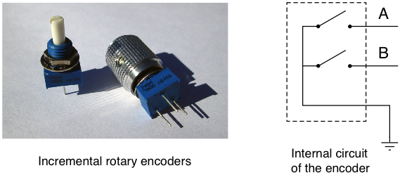
You will need the rotary encoder and the buzzer from the parts bag in your tool kit. The rotary encoder has a blue square base with three pins sticking out and a silver or black knob attached to it. The buzzer is round and black with two pins on the bottom.
The Rotary Encoder (Background Covered in Class)
A rotary encoder is used to determine the angular position of something that rotates. For example, you are building a weather monitoring system and one of the devices providing input to the system is a weather vane that rotates to point in the direction the wind is blowing. The weather vane could be attached to a rotary encoder and the system would read the inputs from the encoder to see what angle the vane is pointing. Rotary encoders are also commonly used in devices that have a knob on them that the user needs to turn to adjust something.
Rotary encoders come in two types: absolute encoders and incremental encoders. An absolute encoder has outputs to provide a binary number for each angular position of the shaft (0000 = 0°, 0001 = 22.5°, 0010 = 45°, etc.) The number of bits the encoder provides determines the resolution of the angle that can encoded. For example a 10-bit absolute encoder can resolve angles to 360 / 1024 = 0.35°.
Incremental encoders, also called quadrature encoders, are also available in a variety of resolutions (16, 64, 256, etc. per revolution) but they only provides information about whether the shaft has been turned clockwise or counter-clockwise from the previous position, nothing about the actual position of the shaft. As the shaft of one of these encoders is turned, it opens and closes two switches to generate two binary signals.
The two switches can be used (when pull-up resistors are installed) to produce as the encoder is rotated two signals that both look like a 50% duty cycle square wave (see below) but they are 90° out of phase with each other, which gives the appearance when drawn that one of the square waves is lagging behind the other by one quarter of a period.
To see how this can work, examine the diagram below and move along the waveforms from left to right as they would be generated when the control is being rotated clockwise. If we consider the two signals as the outputs of state machine where B is the MSB and A is the LSB, then the output code goes through the sequence 00, 01, 11, 10, 00, 01, etc. as the control is rotated.
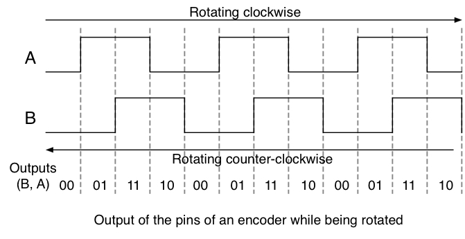
Now try moving along the waveforms from right to left (control being rotated counter-clockwise) and we can see that the output code goes through the sequence 00, 10, 11, 01, 00, etc. as the control is rotated. Note that the sequence is different depending on whether the control is being rotated clockwise or counter-clockwise. In fact every one of the transitions from one two-bit code to another in the clockwise direction is different from the ones that appear when rotating counter-clockwise. As a result whenever there is a code change the direction of rotation can be determined by knowing the old code and the new code.
The above sequences of numbers is called a Gray code and has the property that as you go from one number in the sequence to the next, in either direction, only one bit changes at every transition. Gray codes, usually with many more than two bits in them, are also used in absolute rotary encoders used to encode the position information in electromechanical devices such as scanners, printers, manufacturing equipment and many others. The property that only one bits changes at a time helps to eliminate errors in sensing the device's position. If a normal binary code was used there would be numerous places in the sequence where multiple bits would have to change simultaneously. With mechanical equipment, it's impossible to ensure that all the bits would change at exactly the same time and this can lead to errors as to the position or status of the device.
Using the two-bit Gray code number as a state variable we can construct the state diagram below for a state machine that describes the output of the encoder. Each of the four states corresponds to one of the four sets of output values the control can generate. From each state there are two transitions to an adjacent state, one for each of the code bits that might change. One transition is for clockwise rotation and the other is for counter-clockwise rotation. The direction of rotation is marked on the transition line.
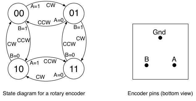
The encoders provided for the lab exercise go through 64 states in the process of one revolution of the knob. The pins on the bottom are arranged with two pins (A and B) on one side, and the pin that goes to ground is on the opposite side. It's not too important which pin is A or B since swapping them only makes the state machine count in the opposite direction for a given direction of rotation.
Task 1 - The Circuit
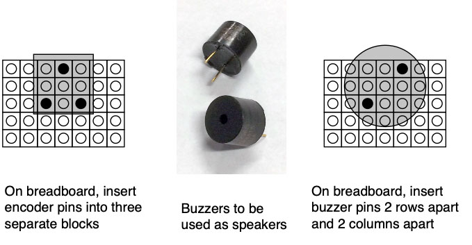
Install the rotary encoder on the breadboard being careful to make sure that all three pins are in different sets of the five hole connections strips (see below). Make the connections between the encoder and the Arduino as shown in schematic diagram below.
Two I/O port bits will be required for reading the encoder output into the Arduino, and one will be required for the buzzer output. To standardize things, everyone should use the A1 and A5 bits (Port C, bits 1 and 5) for the encoder inputs and D12 (Port B, bit 4) for the buzzer output.
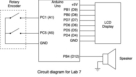
The buzzer has two pins on the bottom and these should be placed in two separate 5-hole connection block as shown below. There is no polarity to the buzzer so it doesn't matter which way it is oriented.
IMPORTANT: If the buzzer is new, it may have a piece of yellow plastic over the top of it. This needs to be peeled off before using it or the buzzer output will be very hard to hear.
Use your male-female jumpers to make the four connections needed between the breadboard and the Arduino as shown in the schematic.
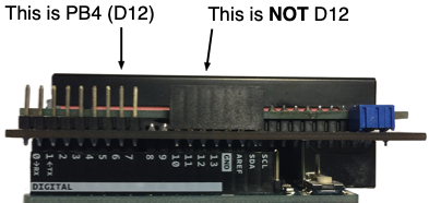
When connecting the buzzer make sure you are using the correct pin on the LCD for D12 (PB4). The D12 pin is marked in white lettering along the row of pins that stick up on the LCD. Don't plug a wire into the black connector above where the Arduino is marked "12" since this is actually the "RX" input to the Arduino and if there is a signal present on that input it can interfere with the "make flash" step.
Task 2 - Confirm Encoder Operation on Oscilloscope
The next task is to use two channels of the oscilloscope to confirm that the encoder outputs are acting correctly as the knob is turned. All that's required from your software for this test is for it to enable the pull up resistors on the encoder input ports, PC1 and PC5.
- Make sure your program contains the line to enable the PC1 and PC5 pull-ups.
PORTC |= (1 << PC1) | (1 << PC5);
- Compile the program and download it into your Arduino..
- Turn on the scope and connect two scope probes to channels 1 and 2 of the scope.
- If it's not lit, press the "2" button below the channel 2 vertical adjustment knob so it lights up. Two traces, one yellow and one green, should show up on the screen.
- Set both channels for 2 volts/division and position one trace near the bottom of the screen and the other about in the middle.
- Set the horizontal scale to 10msec/division.
- Take three wires and plug them into the same three connection blocks that the encoder is plugged in to. These should be in three adjacent blocks with the center one being the ground connection and the two on the sides being for the encoder outputs. You may have to move the encoder and the jumpers to the Arduino around to make space for the wires.
- Connect the two scope probes to the wires coming from the connection blocks with the jumpers going to the A1 and A5 terminals on the Arduino. It doesn't make any difference which probe is connected to which wire. Connect the wire from the middle block to one of the ground clips from both probes. The other clip can be left unconnected.
Try rotating the encoder slowly and see if both traces on the scope go up and down as it's rotated. The scope is showing the states of two encoder output bits. If you rotate slowly you should be able to see it go through the 2-bit Gray code sequence as discussed in class: 00 → 01 → 11 → 10 → 00 …. The main thing to look for is to confirm that both outputs are changing as the encoder is rotated and that the signal levels cover most of the range from ground to 5 volts.
Reading Encoder Inputs
The two inputs from the rotary encoder indicate which of the four states the encoder is in at any time. When reading these two inputs from the encoder, we want to get an accurate reading of which state it is in. If we were to use code like this below there is always the possibility that the state of the encoder could change during the time between when the A input is sampled and the B is sampled later.
    a = PINC & (1 << PC1);
    b = PINC & (1 << PC5);
An even worse method is to sample the A and B inputs many times during a series of "if" clauses each time the value needs to be used. When doing this, the value of A could be a zero at one point but may then change to a one by the time of the next test. This can cause the program to come up with the wrong result in determining which way the encoder rotated.
To avoid this it's better to take one sample of both inputs at the same time, and then use code to find the individual values of A and B from that single sample.
    x = PINC;
    // Now write code to determine "a" and "b" from the "x" value
Now that the values of the A and B encoder inputs have been sampled, these values can be used multiple times in all the "if" statements used to determine what has happened to the count variable.
Task 3: Display Encoder Inputs on LCD
Task 2 showed that the proper encoder signals were reaching the Arduino inputs. In this task we want read these value as discussed above and display them on the LCD. This test will serve to confirm that we can read the two input values into our program and see them changing as the encoder is rotated.
Add code to the main while (1) loop to do the following:
- Read the input bits from the PINC register as discussed above.
- Use a masking operation to store the "A" input in a variable. Note: Remember that the "A" bit is on PC1, so if you just mask off that bit and store the result in a variable the value won't be 1 or 0. How can you fix that?
- Use a masking operation to store the "B" input in a variable. Same warning as above since the "B" bit is on PC5.
- Use
snprintfto create a string with the valueschar buf[10] snprintf(buf, 10, "A=%d B=%d", a, b); - Display the results on the LCD screen using
lcd_movetoandlcd_stringout
Once this code has been added, download it to your Arduino and try rotating the encoder. The A and B values should both be changing, and you should be able to see four separate states that the input values take on. If both inputs are changing, show this to a CP to record that you have the checkpoint task completed for this lab.
Checkpoint: Show that the A and B input values change as the encoder is rotated to a CP for the checkpoint credit.
Task 4: Counting Encoder State Changes Using Polling
Your program will contain a signed variable that starts with a value of zero and then increments or decrements by one for each state change of the encoder outputs. Turning the encoder in one direction increments the count, turning in the opposite direction decrements it. Since there are 64 encoder state changes for each revolution, the count should go up or down 64 each time the encoder is turned one revolution. The count value is not limited to 64, it should continue to grow (positive or negative) as the encoder is rotated. The encoder count will be used to determine the frequency of the tones to be played, but for this task we are not generating the tones, just making sure it counts correctly.
At the start of the lab7.c file some variables are defined for you.
- The frequencies in Hz. of the eight notes are defined in the
frequencyarray. - Variables are defined for holding the state information (
old_state, new_state) and a flag variable (changed) to indicate whether the state has changed. - An int variable,
countis defined to store the count value that the encoder will increment and decrement. This needs to be a signed variable so we can handle positive and negative count values. Your program should start by initializing the count variable to zero and displaying this on the LCD.
This version of the program uses polling to watch the two input bits (Port C, bits 1 and 5) connected to the encoder outputs. The beginning of the program is as follows.
- Add code to enable the pull-up resistors for the A1 and A5 input bits (Port C, bits 1 and 5), set Port B, bit 4 as output, and initialize the LCD.
- As with previous labs, write a splash screen for one second, then clear the screen.
- Read the two encoder bits to determine the initial current state of the encoder (and our initial position in the state machine.)
Following the above code is the main loop of the program:
- Read the two input bits.
- Based on the current state and the input values, find the new state and the new count value. You will have to add the code for this. This is all determined from the state diagram and make sure that your code correctly follows all the transitions in the state diagram.
- If the state has changed:
- Update the count on the LCD. Use snprintf() to generate the string containing the count value and lcd_stringout() to print it.
When you run the program you should be able to rotate the knob back and forth and see the numbers change on the display.
- Check that the numbers change smoothly as the encoder is rotated without skipping or repeating any values.
- Confirm that the numbers can go both positive and negative.
- These encoders go through 64 states per revolution. Confirm that rotating the knob one full revolution in either direction makes the count change by 64.
Playing the Musical Notes
The buzzer will be used to generate the musical notes. The lab7.c file contains a routine, play_note for playing the tones.
For the buzzer to create a tone at a specified frequency, it must be driven by a digital squarewave (50% duty cycle) signal at the proper frequency. The frequency of the squarewave can be adjusted by changing the amount of time the signal is in both the high state and the low state by using the the delay functions in the same way you created a specified waveform in Lab 3. For example, to create a 1kHz squarewave, the period needs to be 1ms, so the signal is high for 0.5ms = 500μs and then low for 500μs before repeating. Our buzzer is connected to the Arduino port D12 (Port B, bit 4) so the code below would work.
    while (1) {  // generate an infinite sequence 1KHz cycles
        PORTB |= (1 << PB4);
        _delay_us(500);
        PORTB &= ~(1 << PB4);
        _delay_us(500);
    }
The less time it is both high and low, the shorter the period and the higher the frequency. If the signal spends more time high and low, the frequency will be lower.
The "lab7.c" file contains an array of 8 "uint16_t" (16-bit) numbers that define the frequencies (in Hz.) of each of the tones that can be generated. These are the tone frequencies that your program should use whenever it generates one of the 8 tones.
    uint16_t frequency[8] =
        { 262, 294, 330, 349, 392, 440, 494, 523 };
The play_note routine take the frequency of the tone as its argument and then generates the tone for one second. It does this by calculating the time in microseconds the signal has to be in the high and low state for that frequency. To implement delays of these times, play_note makes use of another function that is provided for you, variable_delay_us, that takes an argument of the number of microseconds to delay.
The play_note routine generates enough periods of the tone to fill one second. We know how many cycle to generate since that is just the frequency of the signal (number of periods of the signal per second.)
If you examine the code in play_note you will see it does the following:
- Determine the period by converting the frequency (Hz) to microseconds.
- Generate one period of a square wave with the given period. Recall that a square wave is high for half of the period and low for the other half.
- Repeat the above operation the number of times specified by the frequency to generate the tone for one full second.
Task 5 - Generating Tones Based on Encoder Count
Once you are sure the encoder is operating properly and the count value is showing the state changes, you can add the code to generate the tones. The count value is use to determine which musical note is played. Every time the count value is a multiple of 8 (positive or negative) it will play one of eight musical notes for one second. If count is zero, play tone 0 (262Hz). If count is 8 or -8, play tone 1 (294Hz). If count is 16 or -16 play tone 2 (330Hz), etc. Once the count values reach 64 or -64 the sequence should repeat. For example at a count of 64 play the same note as at a count of 0, and at 72 (64+8) play the same note as for a count of 8, etc. The note number (0-7) is defined as:
(|count| modulo 64) / 8
For this task add code to your program to do the following:
- Determine when the count value is a multiple of 8
- Calculate which tone (0-7) needs to be played based on the count value.
- Use that number to look up the frequency in the array.
- Pass this frequency value to
play_note()
Once you have it working, check the following:
- Confirm that a different tone is playing at each multiple of 8 count value
- The sequence repeats when the count reaches 64
- Check that it works with negative count values.
The Problem With Polling and Delay Functions
Using polling to read the encoder inputs, and using a delay function like variable_delay_us to generate the tones, works reasonably well but it has problems that can easily be demonstrated. As the count value is increased or decreased, it has to stop at each multiple of eight and wait for the tone to completely play for one second before it can update the LCD or move on to playing the next tone. While the program is playing the tone, it is not responding to any of the encoder inputs so the count can not change. We would prefer to have the program continue to respond to the encoder and update the LCD with the count value while the tone is playing. While one tone is play, if the count increases or decreases to a different multiple of 8, it should stop playing the old tone and start playing the new one.
The best way to solve this problem is to use interrupts for both the encoder inputs and the tone generation. The encoder inputs will trigger an interrupt anytime they change. Regardless of what the program is doing at the time, the interrupt will cause execution to temporarily go to the interrupt service routine to handle the state change. The program can service the interrupt while executing other code and this should prevent encoder state transitions from being lost. The tone generation will also be changed to one of the timers to implement the delays needed for creating the tones.
For the encoder inputs, we will use the Pin Change Interrupt capability of the microcontroller. All of the I/O pins in the three ports (B, C and D) are capable of generating an interrupt if the pin does a 0→1 or 1→0 transition. The Pin Change Interrupts are ideal for our application of watching for state changes on the two bits from the encoder. Once the Pin Change Interrupts are enabled on the two encoder bits, any change of state will cause the interrupt to occur. The ISR can include the code that determines what state change happened and whether to increment or decrement the count value.
For creating the tones, we will use TIMER1, the 16-bit timer module, to implement the delays rather than using the variable_delay_ms function. TIMER1 was used in Lab 6 to implement a 0.1 second delay for the stopwatch. In this lab it will be used in a similar fashion but the OCR1A value that determines the length of the delay will be changed by the program each time a tone at a different frequency has to be created.
Task 6 - Modify the Program to Use Pin Change Interrupts
We will first change the program to use the pin change interrupts to handle the encoder inputs. Before modifying your program to use interrupts, make a copy of your lab7.c just in case you have to go back to it for some reason.
While individual pins in a port can trigger a Pin Change Interrupt, there is only one interrupt vector (and associated Interrupt Service Routine) for each port.
- Changes on Port B pins invoke PCINT0 → ISR(PCINT0_vect) { ... }
- Changes on Port C pins invoke PCINT1 → ISR(PCINT1_vect) { ... }
- Changes on Port D pins invoke PCINT2 → ISR(PCINT2_vect) { ... }
Pin Change Interrupts for a port are enabled by setting the PCIE0, PCIE1 or PCIE2 bits in the PCICR register. In addition there is an 8-bit mask register (PCMSK0, PCMSK1 and PCMSK2) associated with each port that determines which pins can generate an interrupt. If a bit in the mask register is set to a one, then a 0→1 or 1→0 transition on the corresponding bit in the I/O port will cause a Pin Change Interrupt. If a bit in the mask register is a zero, then changes on the corresponding I/O port bit will not cause an interrupt.
To change the encoder inputs to use interrupts, make the following modifications to the program.
- As with any program that uses interrupts add the following line somewhere near the start of the program if it's not there already.
#include <avr/interrupt.h>
- To get the pin change interrupts working
- Set the PCIE1 bit in the PCICR register to enable the pin change interrupts on Port C (PCINT1).
- Set the bits in the PCMSK1 mask register to enable interrupts for the PC1 and PC5 I/O lines. For PC1 and PC5, these are bits PCINT9 and PCINT13.
- Enable global interrupts.
- An empty "ISR(PCINT1_vect)" interrupt service routine is provided in the lab7.c file and into this routine you should move the code from the main program loop that
- Checks the state of the input bits
- Determines the new state
- Adjusts the count value accordingly
- Sets the "
changed" flag if the state has changed
Some variables may have to be changed from local to global variables. Don't move the code to display the count on the LCD or to play the tone to the ISR. We don't want the microcontroller tied up writing to the LCD or playing the tone while interrupts are disabled in the ISR.
- The main loop of the program should now just check the flag to see if the count value has changed and if so
- Update the displayed value on the LCD
- Determine if a tone should be played.
Any variable that needs to be accessed from both the main program and the ISR must be declared as a global variable at the top of the program (not in the main routine). In addition these variables should be declared with the "volatile" keyword to tell the compiler that their contents can change outside the main stream of code execution.
Task 7 - Using TIMER1 to generate the tones
The last change we want to make to the program is to replace the variable_delay_us function for creating the needed delays with the TIMER1 module. This will involve making changes to the play_note function and adding code to a couple of template functions in the lab7.c file provided for you to complete for this task.
In order for TIMER1 to implement the delays for the notes it has to be able to generate different delays depending on which note is being played. The longest delay will be for the lowest frequency note of 262Hz, and has to be one half the period of that note, or 1/(2 * 262) seconds or 19.08msec. Using the 16MHz clock frequency of the Arduino, this means TIMER1 would have to count to 16,000,000 * 19.08msec = 30,534. Since this number is less than the maximum count value for TIMER1, and all the other frequencies will have smaller count values, it means we can use a prescalar of 1 for all the notes being played, and the count can be calculated as 16,000,000 / (2 * frequency).
Make changes the changes described below to the routines listed.
timer1_init- This routine initializes TIMER1. Use your code from the stopwatch lab assignment to help complete this routine. The two actions this routine must do are:- Set the bits to put TIMER1 in CTC mode.
- Enable interrupts by setting the OCIE1A bit to a one.
Do not set the prescalar bits in this function! Setting the prescalar bits starts the timer running and we don't it running until we need a tone created. In addition you can't set the OCR1A register to a value since that will change each time a tone is created at a different frequency. The OCR1A value will be determined by the
play_notefunction.play_note- For using interrupts, the actions of this routine has to be changed substantially. All the code used with polling and the delay functions can be replaced with the following:- Set a global variable to how many times the ISR needs to run to generate the tone for one second. The frequency (number of cycles per second) of the tone is provided by the
freqargument, and each cycle of the signal requires two transitions. - This routine needs to start TIMER1 by setting its prescalar and modulus values. We have determined above that a precalar of 1 works for all the different frequencies. Using that prescalar, you can write a line of code that calculates the modulus value for a tone of frequency
freqas shown above. This value should be stored in the OCR1A register. - Start the timer by setting the prescalar bits for the prescalar of 1. This starts the timer.
- Set a global variable to how many times the ISR needs to run to generate the tone for one second. The frequency (number of cycles per second) of the tone is provided by the
ISR(TIMER1_COMPA_vect)- The TIMER1 ISR will be invoked each time the output signal to the buzzer needs to change 0→1 or 1→0. Add the code to toggle the PB4 bit each time the ISR is run. In addition, the ISR needs to keep track of how many time it has been invoked. When the ISR has run enough times to create the one second tone at the desired frequency, it should stop TIMER1 buy clearing the prescalar bits to all zeros.
After the changes for the encoder inputs and the use of TIMER1 have been incorporated into the program, try running it and confirm that rotating the encoder still makes the count value go up and down. Once that is working, then try the experiment of rotating the control to reach a multiple of eight, and then continuing to rotate the control while the tone is playing. The count value on the LCD should now change even though the tone is playing. If you rotate the encoder rapidly you should hear it play tones for less than one second and then start playing a different tone.
Results
When your program is running you should be able to confirm the following
- Display your splash screen.
- Count is displayed correctly on the LCD
- Correctly shows positive and negative numbers
- Tones played correctly every 8th count
- Responds to encoder inputs correctly during playing of tones
The answers to the review questions below should be edited into the Lab7_Answers.txt file. The Lab7_Answers.txt file and all source code (lab7.c that uses interrupts, lcd.c, lcd.h and Makefile) must be uploaded to the Vocareum web site by the due date. See the Assignments page of the class web site for a link for uploading.
Please make sure to save all the parts used in this lab in your project box. These will be needed for labs throughout the rest of the semester. We suggest also saving all the pieces of wire you cut and stripped since those will be useful in later labs.
Review Questions
Answer the following questions and submit them in a separate text file ("Lab7_Answers.txt") along with your source code.
- TIMER1 is to be used to output a 50% duty cycle signal (squarewave) for tone generation as was done in this lab. For the two tones specified below, determine a prescalar, the OCR1A value, and the number of interrupts to allow before stopping the timer. Your answer for the prescalar and OCR1A values should be the ones that give the most accurate timing.
- 200 Hz tone for 5 seconds
- 32 Hz tone for 2 seconds
- Briefly explain why updating the LCD display in your ISR could lead to undesirable behavior for this lab.