Lab 5
Rotary Encoders and Interrupts
Honor Statement
This is an individual assignment. The code you write, use for the demo and submit should be wholly your own and not produced by working in teams or using, in part or in whole, code written by someone else (found online, from a fellow student, acquaintance, etc.). Penalties for violation include a 0 on the assignment and a potential further deduction or referral to Student Judicial Affairs.
Introduction
In this lab exercise you will learn how rotary encoders work and how the performance of the program can be improved by using interrupts rather than polling to monitor the inputs from the encoder.
anThe encoder will be used to control the incrementing and decrementing of a signed variable and the value of that variable will be displayed on the LCD shield. Turning the encoder in one direction increments the count, turning in the opposite direction decrements it. Each time the displayed value is a multiple of 8, a brief tone will be generated by a buzzer on the breadboard.
For a copy of the Lab 5 grading sheet, click here
Getting Started
Set up the Lab 5 assignment the same as has been done previously by creating a lab5 folder in your ee109 folder.
- From the class web site, download the file
lab5.zip. This file contains several files that will be used in Lab 5.- lab5.c
- polling.o
- Makefile
- combo-sol.hex
- AGENTs.md
- Extract the files into the
lab5folder. - Add a copy of lcd.c and lcd.h from a previous lab to the lab5 folder.
- If necessary modify the Makefile to work for the Lab 5 files.
Displaying binary numbers
As part of this lab you will have to display on the LCD a number that shows the
value of count variable that is incremented or decremented by turning the
rotary encoder. Up to this point we have only displayed constant strings like
“Hello there” by using the lcd_stringout function. So how can we display the
value of variable that contains some binary value? Many people try doing the
following only to find out that it doesn’t work.
int x = 1234;

lcd_stringout(x);
The “x” variable contains the value 1234. It’s not the name of an array containing the ASCII codes for ‘1’,’2’, ‘3’, ‘4’ and then a zero byte. If we try the above code the LCD will end up with either nothing or garbage displayed on it, and the Arduino’s program may stop running.
It’s important to remember that the LCD only displays ASCII characters.
Any other type of value must somehow be converted into an array of ASCII
characters, a C string, before it can be displayed. In the section below we
will discuss the snprintf function which is used to convert binary variables
to a C string of ASCII codes.
Creating character strings
Since the LCD is used to display strings of characters, it’s necessary to have
a efficient way to create the strings to be displayed. Constant strings are no
problem and can be given as an argument to the lcd_stringout function.
lcd_stringout("Hello, world");
It gets more complicated when you need to create a string containing variable values, such as numbers. For example, in C++ when you write
cout << "Answer is " << x << endl;
cout is converting the numeric value of x into the ASCII representation of that number.
In C, the best tool for creating character strings is the snprintf function
that is a standard part of most C languages. Important: In order use
snprintf, or any other routine from the C standard I/O library, you must have
the following line at the top of the program with the other #include
statements.
#include <stdio.h>
The snprintf function is called in the following manner
snprintf(buffer, size, format, arg1, arg2, arg3, ...);
A quick example is:
char buf[17];
int x = /* some value */
snprintf(buf, 17, "Answer is %d", x);
lcd_stringout(buf);
The arguments for snprintf are:
buffer
The destination char array large enough to hold the resulting string including the NULL byte that has to be at the end. For example, if you want to store 4-digit numbers in a array, the array must be at least 5 elements long.
size
The size of the destination char array. This tells the snprintf program the maximum number of character it can put in buffer regardless of how many you try to make it do. Keep in mind that the snprintf functions always puts a NULL byte at the end of the string it creates. If you call snprintf with a “size” argument of five, and try to put “12345” in the array, you will end up with the string “1234”.
format
The heart of the snprintf function is a character string containing formatting codes that tell the function exactly how you want the following arguments to be formatted in the output string. More on this below.
arguments
After the format argument comes zero or more variables containing the values to be placed in the string according to the formatting codes that appear in the format argument. For every formatting code that appears in the format argument, there must be a corresponding argument containing the value to be formatted.
The Format Argument in snprintf
The format argument tells snprintf how to format the output string. Typical format arguments can contain plain text that is copied verbatim to the output buffer, and formatting codes that specify how to translate the variables into ASCII character codes. There are a large number of formattting codes that can be used depending on how an argument is to be converted to ASCII codes. The formatting codes all start with a percent sign and for now we will only be working with two of them (and a simple variation of one of them):
-
%d - Used to format decimal integer numbers. When this appears in the format string, the corresponding argument will be formatted as an decimal integer number and placed in the output string. It will only place as many characters in the buffer as needed to display the number. A number from 10 to 99 will take up two places, a number from 100 to 999 will take up three places, etc.
A useful variation of this is to specify a minimum field width by using the form “%nd” where the ‘n’ is the minimum number of spaces the converted number should occupy. If it takes less space than ‘n’ characters it will be right justified in the ‘n’ character field with spaces to the left. For example, a format of “%4d” will print an argument of 65 as “ 65” with the number right justified and two leading spaces.
-
%s - Used to format string variables. When this appears in the format string, the corresponding argument will be assumed to be a string variable and the whole string variable will be copied into the output string.
The format string must have the same number of formatting codes as there are arguments that follow the format argument in the function call. Each formatting code tells how to format its corresponding argument. The first code tells how to format “arg1”, the second code is for “arg2”, etc. Anything in the format argument that is not a formatting code will be copied verbatim from the format string to the output string.
Example: Assume you have three unsigned char variables containing the month, day and year values, and a string variable containing the day of the week, and you want to create a string of the form “Date is month/day/year = dayofweek”.
char date[30];
unsigned char month, day, year;
char *dayofweek = "Wednesday";
month = 2
day = 14;
year = 18;

snprintf(date, 30, "Date is %d/%d/%d = %s", month, day, year, dayofweek);
After the function has executed, the array “date” will contain
Date is 2/14/18 = Wednesday
Since you told snprintf that the size of the array was 30, the maximum number of characters it will put in the array is 29 since as with all C strings, the string has to be terminated with a null byte (0x00).
An additional example is shown here:
char x = 10, char y = 12;
char z = x - y;
char buf[12]; // make sure you add one spot for the null character
snprintf(buf, 12, "%d-%d=%d", x, y, z); // yields "10-12=-2" but not on the LCD
lcd_stringout(buf); // prints "10-12=-2" on the LCD
Beautifying Your Output
Often times we may want a number to take up a fixed number of spaces on the
screen. For example if we print out 9 and then 10 the fact that 10 grew
into a 2nd digit may make the visual layout look sloppy. We might want all our
numbers to use 2 digits (if we know in advance that they will be in the range
00-99) or 3 digits (if we know the range will be 0-255). To do this we can add
modifiers to the %d format string modifier.
-
%2dwill print the decimal number using 2 spaces leaving the first space blank for single-digit values 0-9. -
%3dwill print the decimal number using 3 spaces leaving the first one or two blank.
We can also set the string to use 0-padding to fill in blank spaces with 0s.
%03dwill print the decimal number using 3 spaces if needed and fill in unused digits with0s. For example,5would be printed as005, while34would be printed as034.
A good reference for format strings can be found here
Task 1 - Revisiting the 1-Digit Counter
In Lab 3 you built a 1-digit counter that incremented or decremented a number every 500ms, and the UP and DOWN buttons controlled which direction the count was changing. As part of this lab we found that simply putting a 500ms delay in the main loop of the program made it difficult to detect short button presses and you were asked to modify the program to sample the buttons at a much higher rate but continue to change the count every 500ms.
In this task we want to see how this same improvement could have been obtained by using interrupts to detect button presses. Specically we want to use the “Pin Change Interrupt” feature of the microcontroller that will generate an interrupt whenever an input pin changes, such as when a button is pressed and the input changes from 1 to 0.
From the table in front of the podium get a sheet that has the complete code for the 1-digit counter but uses the Pin Change Interrupts. Take note of a few things.
-
The code for determining which button has been pressed has been moved from the main loop to the Interrupt Service Routine near the bottom.
-
All the extra code to sample the buttons at a higher rate has been removed and main loop has a 500ms delay at the end of it.
-
If you compare your code from Lab 3 with this program you will notice how the use of interrupts has allowed the program to be much simpler.
On the sheet, there are several places where code has been left out and there are blank places to write in code to complete the program. You job is to complete the program on the sheet of paper and then show it to one of the teaching staff for credit.
The Rotary Encoder (Background Covered in Introductory Video)
This section is a brief introduction to the rotary encoder that is discussed in more detail in the introductory video that should be watched before attempting to do this lab assignment.
A rotary encoder is used to determine the angular position of something that rotates. For example, you are building a weather monitoring system and one of the devices providing input to the system is a weather vane that rotates to point in the direction the wind is blowing. The weather vane can be attached to a rotary encoder and the system reads the inputs from the encoder to see what angle the vane is pointing. Rotary encoders are also commonly used in devices that have a knob on them that the user needs to turn to adjust something.
Rotary encoders come in two types: absolute encoders and incremental encoders. An absolute encoder has outputs to provide a binary number for each angular position of the shaft (0000 = 0°, 0001 = 22.5°, 0010 = 45°, etc.) The number of bits the encoder provides determines the resolution of the angle that can encoded. For example a 10-bit absolute encoder can resolve angles to 360 / 1024 = 0.35°.
Incremental encoders, also called quadrature encoders, are also available in a variety of resolutions (16, 64, 256, etc. per revolution) but they only provides information about whether the shaft has been turned clockwise or counter-clockwise from the previous position, nothing about the actual position of the shaft. As the shaft of one of these encoders is turned, it opens and closes two switches inside the encoder that generate two binary signals.
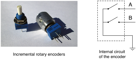
The two switches can be used (when pull-up resistors are installed) to produce as the encoder is rotated two signals that both look like a 50% duty cycle square wave (see below) but they are 90° out of phase with each other, which gives the appearance when drawn that one of the square waves is lagging behind the other by one quarter of a period.
To see how this can work, examine the diagram below and move along the waveforms from left to right as they would be generated when the control is being rotated clockwise. If we consider the two signals as the outputs of state machine where B is the MSB and A is the LSB, then the output code goes through the sequence 00, 01, 11, 10, 00, 01, etc. as the control is rotated.
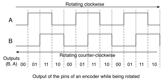
Now try moving along the waveforms from right to left (control being rotated counter-clockwise) and we can see that the output code goes through the sequence 00, 10, 11, 01, 00, etc. as the control is rotated. Note that the sequence is different depending on whether the control is being rotated clockwise or counter-clockwise. In fact every one of the transitions from one two-bit code to another in the clockwise direction is different from the ones that appear when rotating counter-clockwise. As a result whenever there is a code change the direction of rotation can be determined by knowing the old code and the new code.
The above sequences of numbers is called a Gray code and has the property that as you go from one number in the sequence to the next, in either direction, only one bit changes at every transition. Gray codes, usually with many more than two bits in them, are also used in absolute rotary encoders used to encode the position information in electromechanical devices such as scanners, printers, manufacturing equipment and many others. The property that only one bits changes at a time helps to eliminate errors in sensing the device’s position. If a normal binary code was used there would be numerous places in the sequence where multiple bits would have to change simultaneously. With mechanical equipment, it’s impossible to ensure that all the bits would change at exactly the same time and this can lead to errors as to the position or status of the device.
Using the two-bit Gray code number as a state variable we can construct the state diagram below for a state machine that describes the output of the encoder. Each of the four states corresponds to one of the four sets of output values the control can generate. From each state there are two transitions to an adjacent state, one for each of the code bits that might change. One transition is for clockwise rotation and the other is for counter-clockwise rotation. The direction of rotation is marked on the transition line.
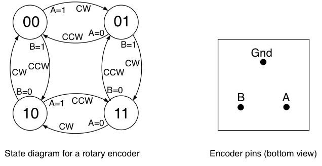
The encoders provided for the lab exercise go through 64 states in the process of one revolution of the knob. The pins on the bottom are arranged with two pins (A and B) on one side, and the pin that goes to ground is on the opposite side. It’s not too important which pin is A or B since swapping them only makes the state machine count in the opposite direction for a given direction of rotation.
Task 2 - The Circuit
You will need the rotary encoder, buzzer and a button from the parts bag in your tool kit. The rotary encoder has a blue square base with three pins sticking out and a silver or black knob attached to it. The buzzer is round and black with two pins on the bottom.
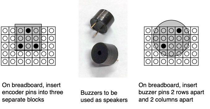
Install the rotary encoder on the breadboard being careful to make sure that all three pins are in different sets of the five hole connections strips (see below). Make the connections between the encoder and the Arduino as shown in schematic diagram below.
Two I/O port bits will be required for reading the encoder output into the Arduino, one will be required for the buzzer output, and one for the button input. To standardize things, everyone should use the A1 and A5 bits (Port C, bits 1 and 5) for the encoder inputs, D12 (Port B, bit 4) for the buzzer output, and A3 (Port C, bit 3) for the button input.
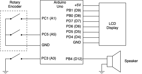
The buzzer has two pins on the bottom and these should be placed in two separate 5-hole connection block as shown below. There is no polarity to the buzzer so it doesn’t matter which way it is oriented.
IMPORTANT: If the buzzer is new, it may have a piece of yellow plastic over the top of it. This needs to be peeled off before using it or the buzzer output will be very hard to hear.
Use your male-female jumpers to make the five connections needed between the breadboard and the Arduino as shown in the schematic.
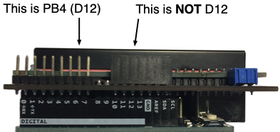
When connecting the buzzer make sure you are using the correct pin on the LCD for D12 (PB4). The D12 pin is marked in white lettering along the row of pins that stick up on the LCD. Don’t plug a wire into the black connector above where the Arduino is marked “12” since this is actually the “RX” input to the Arduino and if there is a signal present on that input it can interfere with the “make flash” step.
Install a button on the breadboard and connect it to Group C, bit 3 (PC3) on the Arduino.
Task 3 - Sampling the Encoder with Polling
In this task you will download code to your Arduino that samples the states of the rotary encoder signals and changes a count value depending on whether the encoder was rotated clockwise or counter clockwise. The program uses polling to sample the encoder, not interrupts, and we want to make some observations as to whether using polling is suitable for this task.
The full program has been written and the binary code for it is in the
“polling.o” file that will be linked to your LCD routines and then downloaded.
Assuming you have the circuit described above in Task 2 wired correctly, you
can download the program using the command make polling.
Once the program is running try slowly rotating the encoder and see if the count value changes. Rotating in one direction should make the number increase, going in the other direction should decrease the number. Try this experiment.
-
Rotate the encoder so the indicator on the knob points to something like one of the corners of the encoder base.
-
Reset the count to zero either by pressing the RST button on the LCD or by doing a
make pollingto reload the program. -
Slowly rotate the encoder one full revolution. The count value should have changed to 64 or -64 depending on which direction you went.
-
Now rotate it slowly in the opposite direction one full revolution and see if the count value goes back to 0.
The above experiment shows that the encoder goes through 64 state changes for a full revolution, and that when done slowly the count value can be correctly determined by the program using polling to sample the encoder signals.
While polling works when the encoder signals change slowly we now want to see what happens when they change more rapidly by doing a second experiment.
-
As was done above rotate the encoder so the indicator on the knob points to something like one of the corners of the encoder base and reset the count value to zero like you did above.
-
Spin the encoder rapidly one full revolution. It’s OK if you have to do this in multiple stages like rotating it 180 degreen quickly and then doing that again to complete the full revolution.
What does the count value show? When the encoder signals change rapidly the program tends to lose track of all the changes and the count probably won’t be 64 or -64 like it was when the encoder was rotated slowly.
Make four observations of the encoder’s result when it’s rotated quickly. Do two rotating it clockwise and two when rotating it counter clockwise. Before each reset the count to zero. Record the count value in the Lab5_Answers.txt file.
Task 4 - Using Interrupts
In this task you will be provided with a program that plays a musical tone on the buzzer based on the count value shown on the LCD. The provided code uses polling to read the encoder signals and it will be your job to convert the program to use the Pin Change Interrupts for better performance.
The lab5.c file that you downloaded from the class web site is a mostly
complete program that uses polling. As the encoder changes the count shown on
the LCD, each time the count is a multiple (positive of negative) of 8, a
different tone is played for one second. There are eight tones defined that
are played for count values of 0, 8, 16, … , 56, and then the sequence
repeats. The same tones are played for negative values of the count.
As part of this task, we want you to practice creating strings that contain variable
values using snprintf(). Look for the portion of the code near the top
where it says to add a “splash screen”. In this section add code to display
two lines of text on the LCD. The first line on the LCD should display your
name (as much as will fit) on the first row. The second row should contain a
string with your birthday that was created using snprintf, similar to the
way the string above was formatted with a date using numerical values and the
“%d” format strings. It should be displayed somewhat centered on the bottom
row and not just start at the 0-th column of the row. This ensures you
understand how to use the lcd_moveto function. After both rows are displayed
on the LCD, make the program delay for 1 second, and then clear the screen.
      /* Call lcd_stringout to print out your name */

      /* Use snprintf to create a string with your birthdate */

      /* Use lcd_moveto to start at an appropriate column
         in the bottom row to appear centered */

      /* Use lcd_stringout to print the birthdate string */

      /* Delay 1 second */

      /* Use lcd_writecommand to clear the screen */
The second part of this task is to convert the program from using polling to read the encoder to using the Pin Change Interrupts. Do to this make following additions and change to the code.
-
Add code to top of the program to configure the Pin Change Interrupts on inputs PC1 and PC5.
-
Create a ISR for Pin Change Interrupts on Port C.
-
Move all the code currently in the main loop that reads the encoder inputs and determines the next state and the value of the
countvarible to the new ISR.
The third part of this task is to correct a few errors in the code. The program has a sequence of “if” statements that detemine which state of the encoder to transition to based on the old state and the current inputs.
A few of these transitions are incorrect and if not fixed will prevent the program from operating correctly. Study the code and compare it with the state diagram shown earlier on the web page. Make any corrections needed to the state transition code so it correctly reflects the operation of the encoder.
Once you have the program modified and fixed download it to the Arduino. Demonstrate its operation to one of the staff in order to receive credit for completing this task.
Task 5 - AI Developement
For this task your goal is to use generative AI to write a prompt that will
create an avr-gcc program that implements the design with the high level
description provided below. We provide a pre-compiled executable of the
desired behavior so that you can RUN the code to derive the functionality,
etc. It should be instructive to consider what details you need to provide
and how to structure your prompt to get the best results without needing too
many iterations.
The design implements a 3-digit number lock that requires the user to enter the
correct 3-digit code to unlock it by using the rotary encoder to alter a number
and the button to move to the next number. The initial secret code is 01 00
09, but can be set to a new code once unlocked by double-clicking the button.
Explore the behavior of this design by running make combo-sol.
To tell the difference between our solution and your implementation, our solution shows a splash screen for 2 seconds that indicates: SOLUTION. Your implementation should change that splash screen to show your name.
Your challenge is to complete a full prompt in the AGENTS.md file provided
(you may not change the instructions provided at the top of that file).
You will need to submit your AGENTS.md file with the prompt(s) you wrote and
demo the resulting code to course staff. Ensure you follow the directions about
specifying your prompts in AGENTS.md.
Results
The answers to the review questions below should be edited into the Lab5_Answers.txt file. The Lab5_Answers.txt file and all source code (lab5.c with the code fixes and using interrupts, lcd.c, lcd.h, Makefile and AGENTS.md) must be uploaded to the Gradescope web site by the due date. See the Assignments page of the class web site for a link for uploading.
Please make sure to save all the parts used in this lab in your project box. These will be needed for labs throughout the rest of the semester. We suggest also saving all the pieces of wire you cut and stripped since those will be useful in later labs.
Review Questions
Answer the following questions and submit them in a separate text file (“Lab5_Answers.txt”) along with your source code.
Question 1. In Task 4 of this lab you worked with a program that produced
tones with the buzzer by creating a 50% duty cycle signal (squarewave) to drive
the buzzer at certain frequencies. This involves changing the state of the
output signal at regular intervals based on the desired frequency. The program
used the _delay_us functions to generate the signal for the buzzer, but it
could have been done much more efficiently by using one of the timer modules.
Assume TIMER1 is to be used to output a 50% duty cycle signal for tone generation. For the two tones specified below, determine a prescalar, the OCR1A value, and the number of interrupts to allow before stopping the timer. Your answer for the prescalar and OCR1A values should be the ones that give the most accurate timing.
-
200 Hz tone for 5 seconds
-
32 Hz tone for 2 seconds
Question 2. If the program in Task 4 was converted to use TIMER1 to generate the tones, briefly explain why updating the LCD display in your ISR could lead to undesirable behavior.
Question 3. Submit the AI-prompts/addendums used to create the source code for the number lock design and provide a detailed, logical description of the system.