Lab 4
Countdown Timer
Honor Statement
This is an individual assignment. The code you write, use for the demo and submit should be wholly your own and not produced by working in teams or using, in part or in whole, code written by someone else (found online, from a fellow student, acquaintance, etc.). Penalties for violation include a 0 on the assignment and a potential further deduction or referral to Student Judicial Affairs.
Introduction
In this lab exercise you will use your Arduino board and the LCD shield to implement the functionality of a digital countdown timer. This lab will incorporate embedded coding concepts from multiple I/O modules including timers and digital I/O in a single project. You may utilize code from other labs or in class demos as modules/functions for this project. <!–
To see a short video demonstrating the operation of lab, click here.
–>
For a copy of the Lab 4 grading sheet, click here.
Getting Started
To get started, create a “lab4” folder, download the lab4.zip file from the
class web site and put it in the “lab4” folder. The zip files contains a
lab4.c file and a Makefile to use for the program and the Lab4_Answers.txt
file for the review questions. Copy your lcd.c and lcd.h files from the lab3
folder to the new lab4 folder.
The lab4.c template file should be used as a starting point for the program. Add code to implement the timer as described below in Task 2.
Before developing the code to implement the timer we want to expand our ability to write strings of characters on the LCD. We will need to be able to move to any location on the LCD and output a string of characters starting at that position.
Displaying Text Strings on the LCD
In many of the EE109 labs we will have to display text of some type on the
screen of the LCD. In the previous lab we used the lcd_writedata function to
display a single character on the LCD, but it would be better if we could
display an entire string of charaction with just one function call, and had the
ability to display the strings anywhere on the screen. In this section we will
learn how to do that.
Character strings in C
The lcd.c file contains a function, lcd_stringout, that will write to the
LCD a string of multiple ASCII characters starting at wherever the LCD cursor
is located. In the C language these are often called “C strings” and are
simply a “char” array containing the characters to be displayed.
It is very important that this array be a proper and correct collection of characters or garbage is likely to end up being displayed on the LCD. A array that holds a string of characters in C has to:
-
Contain any number of printable ASCII character codes. The code for the first character in the string is in array location 0, the next in location 1, etc.
-
Contain a zero byte (also called a “NULL” byte) in the next array location after the last ASCII character to be display. This is just a byte is containing the value zero. The zero byte marks the end of the characters in the string.
There are many ways to create a C string. For example to make a string containing “USC” we could do this.
char school[4] = "USC";
The compiler puts the ASCII code for ‘U’ (0x55) in school[0], the code for
‘S’ (0x53) in school[1], the code for ‘C’ (0x43) in school[2] and puts a
zero byte in school[3]. It’s very important that the array was declared as
size 4 even though we only had 3 characters to put in it since the compiler
needs the extra place in the array for the zero byte.
We could have also assigned the array values individually.
char school[4];

school[0] = 'U';
school[1] = 'S';
school[2] = 'C';
school[3] = 0;
The last line could also have been written as
school[3] = '\0';
but it would NOT be correct to write the last line as
school[3] = '0';
since this assigns school[3] to be the ASCII value of 0 character (0x30).
No matter how the C string is created, it is very important that it is a correctly formatted array with the zero byte at the end. If the array elements do not contain proper ASCII codes, or the zero byte is missing, all sorts of strange things will appear on the LCD when it is sent to the LCD, and the Arduino’s program will probably die at that point.
Displaying strings of characters
To write a string of characters to the LCD, the “lcd.c” file contains the the
function lcd_stringout. This routine writes a string of multiple characters,
as described above, to the LCD starting at the current cursor position. The
argument to lcd_stringout must be pointer to a standard C string, an array of
“char” variables each containing an ASCII character code, terminated by a zero
byte. Normally in programs we just write the name of the array containing the
C string as the function argument and the compiler knows to pass a pointer to
that string when the function is called.
Open up the “lcd.c” file and look at how the lcd_stringout function works.
It contains a loop that does the following:
- Looks at a value in the string (a character)
- If character is the NULL character (i.e. the value of the character variable is zero) that is at the end of all C strings, all the characters in the string have been sent to the LCD so the loop is done and the function returns.
- Otherwise, use the
lcd_writedatafunction to send the character to the LCD. - Move to the next element in the string.
We can pass to the lcd_stringout function an array of ASCII codes either by
our first filling an array in one of the ways shown above, or by just putting
the string in the function call as the argument. For example to print our name
we just need to do
lcd_stringout("Tommy Trojan");
Keep in mind that the lcd_stringout function has no idea where it is writing
characters on the screen. It just writes characters at whatever place on the
screen that the cursor happens to be sitting. To be able to write anywhere on
the screen we need to use another function to tell the LCD where the string
should go.
Moving the Cursor on the LCD
In order to write characters to various places on the display, we need to
ability to move the cursor to one of the 32 character positions prior to
sending the ASCII data. Each character position on the display has a unique
address in the same way that bytes in computer’s memory have unique addresses.
The “lcd.c” file contains the function lcd_moveto that accepts as arguments a
row (0 or 1) and column number (0 to 15) and translates that to the command to
move the cursor to the position with the correct address. For example, to move
the the fifth column (column 4) on the second row (row 1), we would use this
command.
lcd_moveto(1, 4);
The lcd_moveto function is designed to hide from the user the ugly details
about how the LCD actually addresses the characters in the display but instead
just uses a row number (0 or 1) and a column number (0 to 15).
Once the cursor has been moved to a position, any subsequent data bytes sent
will cause characters to appear starting at this position and extending to the
right. Note: if you write more characters than will fit on a line, it doesn’t
automatically wrap to the next line. It just keeps writing characters on that
line even if some go past the right side and can’t be seen. If you want the
additional characters to go on the second line, you have to use lcd_moveto to
position the cursor there before writing the additional characters.
Task 1: Write the Splash Screen
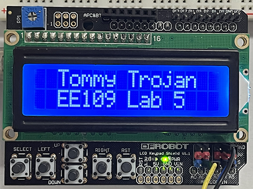
All EE109 labs from now on should have a splash screen on the LCD that shows your name and the which lab it is.
-
In the
lab4.cfile, add code to iniitialize the LCD module by calling thelcd_initfunction. -
In the section of the file that says to add the splash screen, use the
lcd_movetofunction to move to a position on the first line and then uselcd_stringoutto display your name, or as much as will fit. If your name is less than 16 characters, try to center it on the line by adjusting thecolumnargument to thelcd_movetocall. -
Move to the second line and display the name of the lab assignment.
-
Add a call to the
delay_msfunction to delay the program for one second or more so people have time to read the splash screen. -
Call
lcd_writecommandwith an argument of 1 to clear the screen so parts of the splash screen are not left on the display while the rest of the program runs.
Countdown Timer Application
The Arduino and LCD shield will be used to implement a countdown timer application that counts down in increments of tenths of seconds from a time that has been set down to 0.0 seconds. It will provide the ability to set the starting time, and then start, stop, and reset the timer.
Note, while we can use delay functions to cause things to happen every 0.1
seconds, this approach will not give us good results in this lab for several
reasons. Recall that when using delay functions the time is measured only while
the function is executing and it will miss the time associated with the code
checking for button presses or updating the LCD. From previous labs we know
that the time we miss this way accounts for for several milliseconds each
iteration of the loop which adds up to seconds when measuring durations close
to a minute. The alternative approach we will be using in this lab is to use a
hardware timer that runs in parallel to our while (1) loop code that
continuously measures the time. To get updates from the hardware timer at
precise time intervals, we will enable the timer interrupts that will call our
interrupt routine, a special C function.
State Machine Approach
The timer is implemented as a state machine with four states: STOPPED, STARTED, SETSS and SETT that are described below. Three buttons are used to control the action of the timer.
- SST (Start/Stopped/Tens)
- RO (Reset/Ones)
- SET
Presses of the button will cause updates/transitions between the four states as shown below and may cause actions to be taken depending on the transition that occurred. What needs be done in each state should be fairly intuitive. The program will also need some sort of internal representation of the time (more on that below) and logic to decide when to update the display.
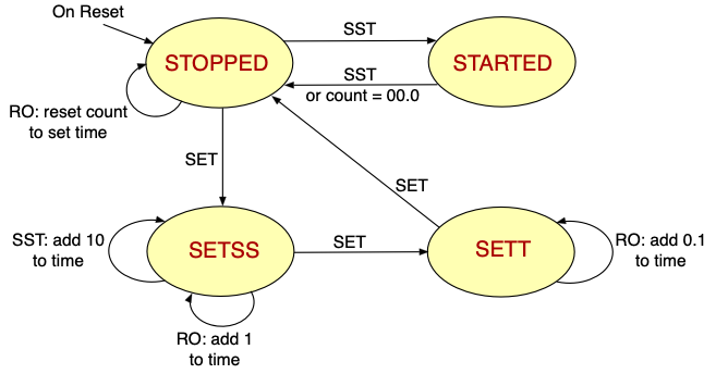
The following summarizes how the state machine works in each state
- STOPPED
- If SST pressed start counting down and transition to STARTED
- If SET pressed transition to SETSS to set the seconds
- If RO pressed, reset countdown time to the set time (i.e. start over)
- STARTED
- If SST pressed stop counting and transition to STOPPED
- When count reaches 00.0 transition to STOPPED state
- SETSS
- On each press of SST add 10 seconds to the count
- On each press of RO add 1 second to the count
- If SET pressed, transition to SETT state
- SETT
- On each press of RO add 0.1 seconds to the count
- If SET pressed, transition to STOPPED state
To summarize, in the STOPPED and STARTED states the SST button toggles the machine between being stopped and counting down. The when STOPPED, SET button take the machine to the state where the seconds can be adjusted, and another press of SET goes to where the tenths can be adjusted. A final press of SET send the machine back to the STOPPED state.
With your text editor open the lab4.c file and look at how it is structured.
The main loop of the program is performing three tasks each time around the
loop:
-
Checks the three buttons for presses
-
Depending on the current state and the button inputs, may take some action and/or change to a different state.
-
If the time to be displayed has changed, update the display to shown the new time.
While that loop is running, your timer module is also running generating interrupts at regular intervals. The main loop and the ISR can be thought of as two separate programs, both running at the same time, that communicate about what needs to happen through the state variable and flag variables. For example, the code in the timer ISR can set a flag variable to indicate that the internal time has changed due to the ISR being invoked. The main program can check this variable, and the state variable, to determine whether the displayed time on the LCD needs to be updated.
Button Inputs
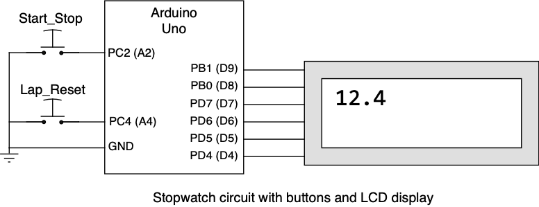
As input to your timer you will use three push-buttons on your breadboard.
-
The button connected to port PC1 will serve as the “START/STOP/TENS” button.
-
The button connected to port PC2 will serve as the “RESET/ONES” button.
-
The button connected to port PC3 will serve as the “SET” button.
Below is a schematic diagram of the circuit for Lab 4.
Task 2: Configure the Timer Module
The counting action of the stopwatch is based on using the 16-bit TIMER1 module to generate an interrupt at regular intervals. For this timer we will have TIMER1 interrupt at intervals of 50ms, and our code will keep track of home many of these intervals have gone by to determine when to update the time displayed on the LCD.
In order to make TIMER1 interrupt every 50ms several things have to be done to initialize it.
Step 1: Find the counter modulus and prescaler values
The counter need to be configured to count up to a specified value at some counting rate so it reaches that value after exactly the amount of time required has elapsed. Configuring the timer requires determing these two values: the counting rate and the value to count to.
To find these, first calculate the number of processor clock cycle that happen during this time period. The Arduino uses a 16mHZ clock, and for our timer we want to have a 50ms second elapsed time between interrupts. If there are 16 million clock periods in one second, then in 50ms second we will have 800,000 clock periods. If our timer counts at the rate of 16mHz from 0 to 800,000, then 50ms will have gone by. Next, determine if this number, 800,000 will work with TIMER1. TIMER1 is a 16-bit timer so the number to count up to must fit within 16-bits. The maximum 16-bit number is 65,535, so 800,000 is way too big. To fix this we need to slow TIMER1 down so it not counting as fast and we can then use a smaller number to count up to.
TIMER1 incorporates a “prescaler” which can be used to divide the incoming 16mHz clock down to a lower frequency. You can’t select any arbitrary divisor for the prescalar but have to use one of four possible divisors: 8, 64, 256 or 1024. Each of these divide the 16mHz clock down to a lower frequency which means TIMER1 is counting slower, and as a result the number it counts up to can be smaller for same amount of elapsed time.
For example, suppose our TIMER1 prescalar could divide by 4 (it can’t but we’ll use that number for this example). Using this prescalar value TIMER1 is now counting at a 16mHz/4 = 4mHz rate, and it would need to count to 800,000/4 = 200,000 to implement a 50ms elapased time.
To find a prescalar value that works for the stopwatch, try each of the possible prescalar values (8, 64,256,1024) to see which one results in counter modulus value that fits within a 16-bit number for implementing a 50ms counter interval. You are looking for a count modulus that
- fits in a 16-bit number so can’t be larger than 65,535
- gives an integer modulus value if possible
If there are more than one pair of prescalar and counter modulus that meet these two requirement, you can just pick any of the pairs to use.
Step 2: Determine the TIMER1 register contents
Assuming you found a prescalar and counter modulus value that result in a 50ms timer interrupt interval, you can now determine how the bits in the TIMER1 register must be set to implement the interval.
-
The prescalar is controlled by the three bits, CS12, CS11 and CS10 bits, in the TCCR1B register. It can be set to divide the 16MHz clock by 8, 64, 256 or 1024 depending on the state of these bits.
- CS12:10 = 010 for divide by 8
- CS12:10 = 011 for divide by 64
- CS12:10 = 100 for divide by 256
- CS12:10 = 101 for divide by 1024
-
The modulus value is stored in the OCR1A register and can be any 16-bit value from 1 to 65535.
Once the prescalar bits are set to a value that selects one of these divisors, the timer starts counting. Conversely, if you want to stop the timer at any point, setting the three prescalar selection bits to 000 turns the prescaler off and this stops the counting of the timer. The timer is effectively turned on and off by changing the prescaler settings in register TCCR1B.
For more detailed information on using the timer, refer to the timer lecture notes that are linked in the Lab 4 section of the Labs web page.
Important: The information provided in the slides and video about setting up the timer were for generating interrupts every 0.25 seconds. That was just an example of configuring the timer and is not the timer interrupt interval you are using in this lab.
Step 3: Add code to lab4.c for TIMER1
It’s now time to add a small amount of code to the lab4.c file to allow testing of the TIMER1 to confirm that it’s generating interrupts every 50ms.
In the lab4.c file, look for three functions near the bottom of the file:
timer1_init, timer1_start, and timer1_stop. You will need to add few
lines to these functions.
The timer1_init routine is called once at the start of the program and
configures TIMER1 to produce interrupts every 50ms. There are already
two lines in the function that set how the timer operates and enables it to
generate interrupts. After these lines add code to store the value you
determined above for the counter modules in the OCR1A register.
The timer1_start function is called to start the operation of the timer by
setting the prescalar bits to the values you determined above. Add code to
configure the CS12, CS11 and CS10 bits in the TCCR1B register to the setting
you determined above. Note that this should be done using the symbolic names
of the bits, not by using the number of the bit position. For example, if you
want to set the CS12 bit to a one, the following code will work.
TCCR1B |= (1 << CS12);
The timer1_stop function is used to stop the timer from counting and generating
interrupts. As described above, the timer is stopped by clearing the CS12, CS11
and CS10 bits in the TCCR1B register all to zeros. Add code to the timer1_stop
function to clear these bits.
Task 3: Calculate TIMER Parameters
Before continuing with the development of the countdown timer, students must calculate the answers to some TIMER questions shown below. These should be answered a sheet of paper that is available from the table in front of the VHE 205 podium.
For these questions you can assume the Arduino Uno clock frequency of 16MHz,
and the each timer is operating in CTC mode and resets when its counter matches
OCRnA.
| Timer | Counter Width | Maximum OCRnA value | Available Prescalars |
|---|---|---|---|
| TIMER0 | 8 bits | 255 | 1, 8, 64, 256, 1024 |
| TIMER1 | 16 bits | 65535 | 1, 8, 64, 256, 1024 |
| TIMER2 | 8 bits | 255 | 1, 8, 32, 64, 128, 256, 1024 |
For problems that ask you to select both OCRnA and a prescaler, choose the
smallest prescaler that permits an exact answer. Otherwise, some intervals may
have more than one correct configuration. Refer to equation on slide 13 of
Unit C - Timers and reprinted below to help solve the following problems.

Part A: Find the Time Interval
-
TIMER1usesOCR1A = 50,000and a prescaler of 64. Find the timer interval between interrupts. -
TIMER2usesOCR2A = 250and a prescaler of 32. Find the timer interval between interrupts. -
TIMER1usesOCR1A = 62500and a prescaler of 256. Find the timer interval between interrupts.
Part B: Find OCRnA and the Prescaler. For each problem, choose the smallest
available prescaler that produces the requested interval exactly.
-
Configure
TIMER0for a timer interval between interrupts of 100μs. -
Configure
TIMER1for a timer interval between interrupts of 4ms. -
Configure
TIMER2for a timer interval between interrupts of 4ms.
Once you have calculated the answers to the above questions and recorded your answers on the paper copy, show it to one of the teaching staff to receive credit for finishing this part of the assignment.
Task 4: Test the Timer Module
In this task we want to have the program generate a signal every time the timer interrupts to confirm that you have configured it properly for interrupts every 50ms. In a previous section above you wrote the code to initialize and start TIMER1 to generate interrupts at that rate. Now make these additions to the lab4.c file to produce the test signal.
-
Find the comment about initializing TIMER1 and below that add a line to call the
timer1_initfunction. -
Find the comment about enabling interrupts and below that add an
sei()function call. -
Find the comment about making PB5 an outout and below that add a line to set bit 5 in DDRB to a 1 to make it an output.
-
Just before the main
while (1)loop start add the linetimer1_start();to start TIMER1. -
In the ISR for TIMER1_COMP_vect, add the line
PORTB ^= (1 << 5); -
Make any necessary changes to the Makefile
This compiles the code to have the TIMER1 ISR do an XOR operation on the PC5 bit that can be observed with the oscilloscope. The XOR operation will flip the PB5 bit the other state (0→1 or 1→0) each time the ISR is executed. If the scope shows this bit changing every 50ms then we know your code has correctly configured TIMER1.
Download the code to your Arduino with the make flash command and
connect a scope probe to the PB5 pin to observe the signal. If the ISR is
running every 50ms, this should create a squarewave signal on PB5 with a
rising or falling edge every 50ms resulting in a signal frequency of 10
Hz.
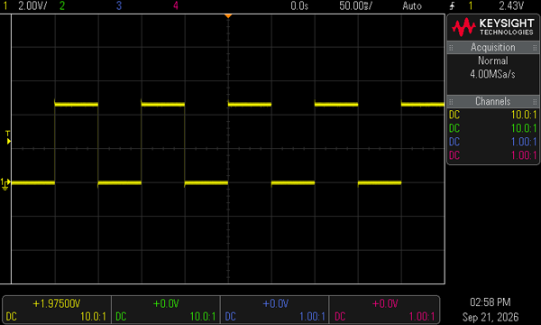
Show one of the teaching staff the 10 Hz test signal from PB5 on the scope to receive credit for completing this part of the assignment.
Task 5: Counting Down
The first part of getting our countdown timer to work is to make it just do the counting down from some time setting to 00.0. This only involves getting the code in the STOPPED and STARTED states work. The states for setting the time will be done later.
The countdown timer must keep track of the time that is changing every 0.1 seconds. Rather that use a “float” variable for this, we will use three separate “char” variables, one each for the tens, the ones and the tenths of seconds. The TIMER1 ISR will be responsible for changing these values whenever another 0.1 seconds has elapsed.
-
Add global variable declarations near the top of the program for the three varibles that will hold the current time value.
-
Add code to read the value of the SST button. This button controls the transitions between the STOPPED and STARTED state. This button will have to be debounced and a function for debouncing the buttons on Group C has been included in the code.
-
In the STOPPED state, if SST has been pressed add code to start TIMER1 and change to the STARTED state.
-
In the STARTED state, if SST has been pressed add code to stop TIMER1 and change to the STOPPED state. In this state it also needs to check if the count has reached 00.0 and if so stop TIMER1 and transition to the STOPPED state.
The bulk of the work in the counting down is done in the TIMER1 ISR. It is being invoked every 50ms but must determine if 0.1 seconds (100ms) has gone by and it’s time to change the time values. This means it will change the time value every 2nd time it is invoked.
-
In the TIMER1 ISR, add code to see if 0.1 seconds has elapsed since the last time the ISR was run.
-
If it’s time to change the time value, do so by modifying one or more of the three global variables.
-
If the time value was changed, set a flag variable to indicate the LCD display needs to be updated. Don’t update the LCD from within the ISR since we don’t want to do long operations while in an ISR. A function
displayTimehas been provided to do this and this function should only be called in the main program not from within the ISR.
To test the countdown timer, add code before the main while (1) loop to set
the three time variables for tens, ones and tenths to some arbitrary numbers
like 2, 3, and 4. This will be the starting time for the countdown timer.
When the SST button is pressed it should transition to the STARTED start an
begin decrementing this value. Observe the LCD display and confirm the following.
-
The numbers change at the correct rate with the tenths decrementing every 0.1 seconds.
-
The number correctly wrap around when one digit is zero by decrementing the number in the next column.
-
When the count reaches 00.0 the counting down stops.
Show one of the teaching staff that your countdown timer is operationg correctly with the test values to receive credit for completing this part of the assignment.
Task 6: Setting the Timer Values
Setting the time the counter counts down from is done from the SETSS and SETT states.
In the SETSS state, pressing the SST button adds 10 seconds to the time. Pressing the RO button adds 1 second to the time. The SETSS state is indicated on the LCD by putting two ‘^’ characters on the line below the tens and ones digits to show that these are numbers that can be changed in this state. Another press of the SET button will transition the device to the SETT state.
In the SETT state, pressing the RO button adds 0.1 seconds to the time. The SETT state is indicated on the LCD by a ‘^’ character on the line below the tenths digit. Another press of the SET button will transition the device to the STOPPED state.
For all three numbers, incrementing it past 9 causes it to wrap around and be set to zero.
While in the SETSS or SETT states, the LED on Group B, bit 5 blinks at a 2Hz rate.
Results
When your program is running you should be able to confirm the following
-
Display your splash screen.
-
The SET button puts the device into the state where the time value can be changed.
-
In the SETSS state the tens and ones can be adjusted.
-
In the SETT state the tenths can be adjusted.
-
Pressing the SST button starts the timer counting down.
-
The timing rate appears to be correct, not too fast or too slow.
-
Counting down can be stopped and started multiple times using the SST button.
-
Counting stops when 00.0 is reached.
-
When in STOPPED state pressing RO resets the time to what was previously set.
The answers to the review questions below should be edited into the Lab4_Answers.txt file. The Lab4_Answers.txt file and all source code (lab4.c, lcd.c, lcd.h and Makefile) must be uploaded to the Gradescope web site by the due date. See the Assignments page of the class web site for a link for uploading.
Please make sure to save all the parts used in this lab in your project box. These will be needed for labs throughout the rest of the semester. We suggest also saving all the pieces of wire you cut and stripped since those will be useful in later labs.
Review Questions
Answer the following questions and submit them in a separate text file (“Lab4_Answers.txt”) along with your source code.
-
Review the conceptual operation of a timer interrupt.
- For a 16-bit timer with clock frequency of 16MHz (like the Arduino) and prescalar of 64, how much time corresponds to a timer value of 2000?
- With a clock frequency of 16MHz and prescalar of 8, what is the longest amount of time we can track with an 8-bit hardware timer.
-
The Timer modules we have used also have the ability to make an output pin turn ON (set), OFF (clear), or Toggle when the timer reaches the OCR1A or OCR1B values (i.e. the hardware can automatically control the output value of a pin). By searching the data sheet (ATmega328P datasheet is linked on our website from the Resources page) answer the following question:
- TIMER1 (the 16-bit timer) can control the pins that are associated with OC1A and OC1B signals. Find to what pins these signals are wired by looking at Figure 1.1 ("28 PDIP" package diagram) on page 12 of the data sheet, or alternatively, Tables 14-3, 14-6, or 14-9.
- In this lab we use TIMER1 in the ``Clear Timer on Compare'' or CTC mode. In this mode when the counter reaches the value in OCR1A register it generates an interrupt and starts counting again from zero. Using the information in section 16.11.1 and table 16-1, describe what the OC1A and OC1B pins would do when the timer reaches the OCR1A value if during initialization we used the statement `TCCR1A = 0x60;`