Lab 3
Arduino Input and Output
Honor Statement
This is an individual assignment. The code you write, use for the demo and
submit should be wholly your own and not produced by working in teams or using,
in part or in whole, code written by someone else (found online, from a fellow
student, acquaintance, etc.). You will be asked to verify this when you submit
your code on Vocareum by signing your name in the honor.txt file on Vocareum.
Penalties for violation include a 0 on the assignment and a potential further
deduction or referral to Office of Academic Integrity (OAI, used to be SJACS).
Introduction
In this lab exercise you will build a signaling device that makes an LED flash the Morse code signal for a letter of the alphabet. Rather than have 26 input buttons it will only have three, each assigned to one of three letters of the alphabet. When one of the buttons is pressed, an LED will flash the Morse code signal for the corresponding letter.
For a copy of the Lab 3 grading sheet, click here.
Morse Code
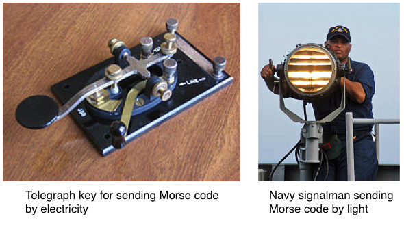
Morse code is a method of signaling letters and numbers by sending on and off patterns of light or audible tones. It was first developed in the 1830’s and for many years was the standard way of communicating via telegraph and radio. It is still used today by amateur radio operators, the military, and sometimes for emergency communication.
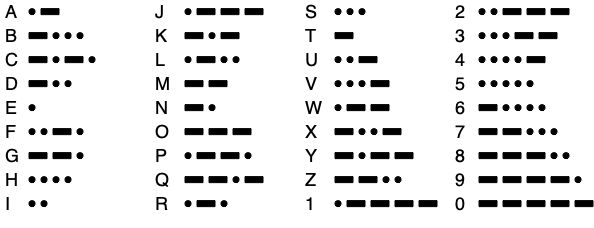
Characters in Morse code consist of a unique set of short or long signals, known as “dots” and “dashes”. The codes for letters A through Z and 0 through 9 are shown below. The dots and dashes of a character are separated by a short gap, and a longer gap separates characters. The most widely known Morse code sequence is the distress call “SOS” of three dots, three dashes, three dots.
The length in time of a dot or dash in Morse code is not specified directly, only the relationship between the dot and dash length:
- Dashes are three times longer than a dot.
- Gaps between the dots and dashes of a single character are the same length as the dot.
- The gap between characters is the length of the dash.
The speed of the transmission of the characters can cover a wide range, but the above ratios must be adhered to in order to make the transmission understandable by the receiving party.
To see a short video demonstrating the operation of this lab, click here.
Buttons
The buttons you will be using are the same ones you used in Labs 1 and 2. These are classified as momentary action, single pole, normally open buttons. These terms define how the button works.
- Momentary action - The button is in the ON state only when it is held down. Once you release pressure on the button, it returns to the OFF state on its own.
- Single pole - The button has one on-off circuit inside it. Buttons can be found with 2, 3, or more circuits that all turn on and off together when the button is operated.
- Normally open - When the button is NOT being pressed the switch contacts aree OPEN so the two terminals of the switch are not connected. Pressing the switch closes the contacts. Switches are also available as “normally closed” models meaning that the contacts are connected (closed) until the switch is pressed.
The buttons have four pins on the bottom that are spaced so they will fit in the holes in the breadboard. When the button is held with two pins at the top and two at the bottom as shown in the diagram on the left below, the left two pins are permanently electrically connected together and the same for the right pair. When the switch operates, it opens and closes the connection between the two pairs of pins as shown below.
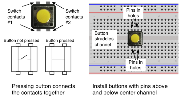
When installing the button on the breadboard, it should be oriented so it straddles the center channel with the two upper pins in two different 5-hole rows, and the same for the two lower pins. When done that way, the switch opens and closes the connection between the two rows of the breadboard holes. Since the upper and lower pins are wired together for both contacts, you can make electrical connections to either one.
LEDs
We used LEDs in Labs 1 and 2 connecting them to electronic circuits. In this lab you will be connecting one to a port bit of the Arduino configured to be an output and your program will determine whether it is on or off. As before, the LED will need a resistor in series with it to limit the amount of current flowing through the LED. Recall that in Lab 1, the current through the LED and resistor was given by
I = (Vs - VLED)/R
where Vs is the source voltage, VLED is the voltage drop across the LED and R is the resistance. When an output bit is in the high state the voltage on the pin is close to 5V so we can assume Vs = 5V, and VLED is usually close to 2V. If we use a 240Ω resistor this will result in a current through the LED of
I = (Vs - VLED)/R = (5 - 2)/240 = 12.5mA
The LED must be oriented so the anode (positive end) is towards the Arduino and the cathode (negative end) is towards ground. The resistor can be in series with the LED either between the Arduino and the LED, or between the LED and ground.
The Circuit
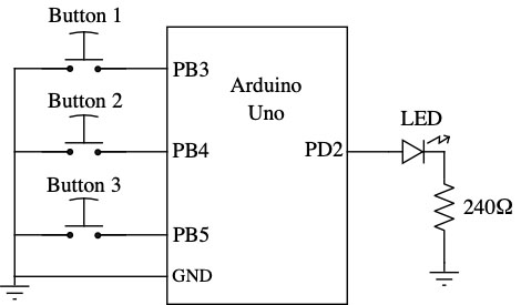
The figures below show a circuit similar to the one you will be building with three buttons for input and an LED for output.
-
The three switch inputs are wired to three of the Arduino inputs. The figure below shows them going to D11, D12 and D13, which are connected to Port B, bits 3, 4 and 5 of the microcontroller, but your circuit will be using different input ports.
-
The LED and current limiting resistor are connected to one of Arduino outputs. The figure below shows a connection to D2 of the Arduino, which is Port D, bit 2 of the microcontroller, but your circuit will be using a different port bit.
-
The ground wire from the Arduino to the breadboard goes to one of the rows of holes that forms the buses that runs the length of the breadboard. Use one of the buses by the blue line for ground. The ground connections to the switch and the resistor can all be made to the holes in that bus row.

Task 1: A Confusing Situation
One of your coworkers on this project has written all the software for reading
the button inputs and generating the output signal and has now left it up to
you to finish the hardware part of the project. Unfortunately they have
neglected to send you the source code for the project but instead have only
sent you the compiled code in a “morse.o” file. Without the source code
there is no quick way to determine which digital I/O bits are used for the
inputs and output. The only hint they provided is that the three input
signals are somewhere on group D, bits 2 through 7 (DIG2-DIG7), or group B,
bits 0 through 4 (DIG8-DIG12), and the output signal is somewhere on group
C, bits 0 through 5 (A0-A5).
It will be your task to figure out which port bits are for the inputs and which is for the LED output by using the test equipment to make observations of the circuit’s behavior.
Do the following steps to get started.
-
In your ee109 folder create a lab3 subfolder.
-
To the lab3 folder download the file
lab3.zipfrom the class web site. Extract the files from it:morse.o- The compiled object file for the Morse code Lab 3 program.uscid.c- A C file you will use to customize the program in the Arduino.lab3.c- A C file you will use later in the lab assignment to implement blinking the LED at different rates.Makefile- A Makefile for use with the morse.o and uscid.c files.- Lab3_Answers.txt - Edit to answer the review problems at the end of this web page.
-
If necessary, edit the Makefile to change PROGRAMMER line as done before to be compatible with your computer.
-
As was done in Lab 2, open the
uscid.cfile with your text editor. It only has a couple of lines and should look like this.#define USCID 1234567890 unsigned long long hash = USCID;
-
Use your text editor to change the 10 digit number on the first line to be your USCid number (without any dashes), and then save and close the file.
-
Plug one end of the USB cable from your lab kit into the USB connector on the Arduino board, and plug the other end of the cable into a port on your computer. If your computer only has USB-C ports, you will need to buy a USB-A to USB-C adapter.
-
Type the command “
make flash” to build and download the Lab 3 program to your Arduino.
Finding the input ports
The Morse code generating program is now running on your Arduino, but unfortunately we don’t know which ports are being used as the button inputs. However we do know that the buttons all require pull-up resistors on them so the buttons can provide 0V and +5V inputs depending on whether they are pressed or not. We can assume that the program has enabled the internal pull-up resistor for each of the three switch input port bits. The other port bits that are not used as button inputs will not have their pull-ups enabled, and the voltage on those port bits is floating and will likely be under 1V.
We can measure the voltage on the port bits with either the DMM or the oscilloscope.
-
Configure the scope or DMM to measure voltage.
-
Make sure to make a connection between the scope probe’s ground lead or the DMM black test lead to one of the ground pins on the Arduino.
-
Using a short piece of wire that you can clip the scope probe or DMM test lead to, proceed to plug it into all the port bits from D2 (group D, bit 2) to D12 (group B, bit 4) looking for any digital I/O bits that have something around 5V present on the pin.
-
Check all these 11 port bits on ports B and D until you have found the three that have their pull-up resistors enabled.
-
Make connections between the buttons on the breadboard and these three port bits as shown in diagram above. Note that as of this time we don’t know which of the three inputs generate each of the three Morse code letters, but we can figure that out once we find out where the output is generated and adjust the wiring accordingly.
Finding the output port
Now that we have the buttons connected to the three input ports that the program is monitoring to produce the Morse code output we can search for the port bit being used for the output. We know it’s somewhere on port C, bits 0 through 5 but not sure which one. Your circuit can produce an output by pressing one of the buttons, so you can check each of the possible port C bits to see which has a signal appear after a button is pressed. This is best done with the scope but the DMM can also be used if necessary.
-
As before make a connection between the scope’s ground lead or the DMM ground lead to the circuit ground on the breadboard.
-
Using a short piece of wire attached to your test lead, plug it into the A0 bit (port C, bit 0) on the Arduino.
-
Press one of the buttons and see if a signal appears on the scope that goes to around 5V back to 0V. If so, this port bit is the one being used for the output.
-
If no signal appeared in the step above, move the wire to the next port C bit and repeat the test. Continue this until you find the port C bit that the program is using for the output.
Once you have determined the output port, make the wiring connections shown above with the LED and current limiting resistor so the LED will flash the Morse code.
Finding the correct switch connections
With the input port bits and the output port bit found, the only thing left to complete the circuit is connecting the correct switch to each of the three input bits.
-
Press button 1 and see which letter, ‘U’, ‘S’, or ‘C’ is flashed on the LED.
-
If it’s not the ‘U’, try the other buttons to see which generates the ‘U’ and then swap the wiring around so button 1 is the ‘U’ button.
-
Repeat the above to find out which input port bit is for the ‘S’ and the ‘C’ and make any necessary wiring changes so button 2 generates the ‘S’ and button 3 generates the ‘C’.
When you have the circuit working so you know which button causes each of the three letters to be displayed in Morse code, show it to one of the instructors so they can record this on your grading sheet.
Task 2: Checking the Timing of the Output
At the start of this lab we specified the timing requirement for correctly sending the dots and dashes of Morse code characters.
- Dashes are three times longer than a dot.
- Gaps between the dots and dashes of a single character are the same length as the dot.
For this task you will use the oscilloscope to examine the output of the three characters and determine if any of them are being sent incorrectly in that the above timing specifications are not being followed.
-
Turn on the scope and connect the two probes to channels 1 and 2.
-
Turn on both channels by pressing the ‘1’ and ‘2’ buttons until they are lit.
-
Set the vertical controls for both channels for 2 volts/division.
-
Use the vertical position controls to put the yellow channel 1 line in the upper part of the display just above the center of the screen, and the green channel 2 line in the bottom part.
-
Set the horizontal control to 500ms per division. This can be changed later to get a good view of signals.
-
Hook the oscilloscope ground connection to the ground on your breadboard.
-
Channel 1 will be used to view the button press signal. Connect probe 1 to the ‘U’ button output where the wire is going to the input bit for the ‘U’ character.
-
Channel 2 will show the output signal going to the LED. Connect probe 2 to the anode of the LED where the wire from the output bit is connected to the LED. Make sure you have the scope probe connected directly to the output port and not after the LED or the resistor.
-
You need the scope to trigger when the button is pressed so adjust the trigger settings so the scope triggers on a falling edge on channel 1. Press the “Trigger” button in the Trigger section of controls and use the buttons below the screen and the Trigger Level knob to make these settings:
- Set “Trigger Type” to “Edge”.
- Set “Source” to “1”.
- Set “Slope” to a falling edge.
- Adjust the trigger level to about 2 volts.
-
The scope is now be ready to trigger when the ‘U’ button is pressed. Press the “Single” button in the upper right to make it wait for the next trigger signal, and then press the ‘U’ button on your breadboard.
-
If everything is working, you will get a display like that below. The yellow trace is showing the signal from the button you pressed. The green trace is showing the Arduino outputting the Morse code for the ‘U’. Use the horizontal controls to adjust the scope timing and position to get a good view of the signal. Check that the timing is correct for the dots, dashes and the gaps between them.
-
If you find a error in the timing, make a note of this on your grading sheet stating which character is incorrect and the nature of the error.
-
Repeat the above steps for the ‘S’ and ‘C’ characters.
When you have finished looking for timing errors, show your findings to one of the instructors so they can record this on your grading sheet.

Task 3: Fixing the Program
For this task you will be fixing the Morse code program to remove any timing errors you found above.
From the podium, get a sheet that has the skeleton of the program for the Morse code program. Complete the program (on the paper) by filling in the missing parts so that the program would correctly generate the ‘U’, ‘S’ and ‘C’ characters if it were downloaded to your Arduino. Use the port bits that you found above for reading the inputs and generating the output.
A portion of the sheet you will be working with is shown below.
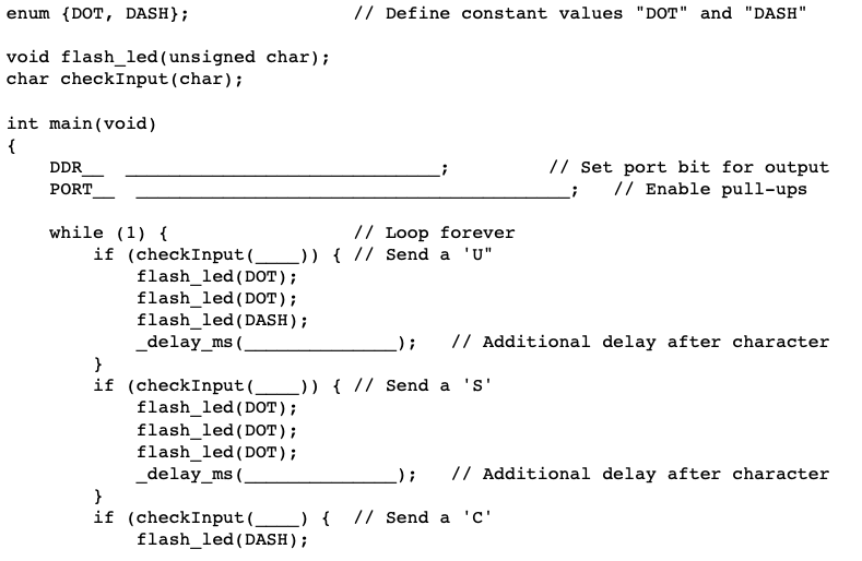
When you have completed fixing the program, show it to one of the instructors so they can record this on your grading sheet.
Task 4: Blinking at Two Rates
For this part of the lab you will write code to read the state of the three buttons and blink the LED at two different rates depending on how many buttons are being pressed.
The file you downloaded previously, lab3.c, will be used for this part of
the assignement. Before starting to edit this file, use your editor to change
the OBJECTS line in the Makefile in the lab3 folder from
OBJECTS = morse.o uscid.o
to
OBJECTS = lab3.o
so the correct file will be compiled when you do a make flash.
Using the lab3.c file as a skelton to get started, add code to implement the
functions described below.
-
If less than two buttons are pressed, blink the LED continuously at a 5Hz rate (on for 100ms, off for 100ms).
-
If two or more buttons are pressed, blink the LED continuously at a 1Hz rate (on for 500ms, off for 500ms)
Your code should monitor the three input buttons but only switch to the other blink rate after completing one cycle (LED on, LED off) at the current blink frequency. In other words, it should not change blink rates in the middle of a blink cycle but should finish a blink at one rate before changing to the other.
When you have this part of the assignment working, show it to one of the instructors so they can record this on your grading sheet.
Results
For each of the tasks described above, once you have the task completed demonstrate it or show the results to one of the instructors. Have them fill out a grade sheet indicating your score for each task. You should keep the paper copy of your grade sheet for this lab in your files for the rest of the semester.
The answers to the review questions below should be edited into the “Lab3_Answers.txt” file. The “Lab3_Answers.txt” file and all source code (lab3.c and Makefile) must be uploaded to the Vocareum web site by the due date. See the Labs page of the class web site for a link for uploading.
Review Questions
Answer the following questions and submit them in a separate text file (“Lab3_Answers.txt”) along with your source code.
-
Suppose our design for the Morse code generator had the three buttons on group D, bits 5-3, with the LED attached to group D, bit 2. Assuming appropriate
DDRDvalues, consider the following method of turning on the LED.PORTD = 0x04; // turn on the LEDExplain the problem with this approach and, in particular, what would stop working after the execution of that line of code.
-
In Lab 1 we built a simple combinational circuit with a button, NOT gate and LED output. In Lab 2 we measured the propagation delay through that circuit from button to LED and found it to be on the order of 10ns. In our circuit this week using software to turn the LED on the delay is much longer, on the order of 1-10 microseconds. That is about two orders of magnitude difference. Software takes much longer because our loop is composed of many software instructions that the processor must fetch from memory, decode and then execute. You can see that if computation needs to be done quickly, hardware has advantages!
In our hardware-only circuit from Lab 2 the gate never changes so the delay time from when the button was pressed to the LED lighting up was fairly consistent, always about 10ns. However, with the Arduino the delay times will vary every time the button is pressed as shown in the two pictures below where the image on the left shows a delay of about 3μs while the one on the right shows a delay around 10μs. Can you explain why the propagation delays vary from one test to another?
Hint: ignore the hardware propagation delays which are very small (tens of ns), and think about how your program executes.