Lab 1
Electronic Circuits
Introduction
This lab assignment has two purposes: to give you some experience assembling basic electronic circuits on the breadboard from your project box and using a couple of pieces of test equipment in the VHE 205 lab. Various circuits will be constructed and the test equipment will be used to make measurements to confirm some of the fundamental laws that apply to electronic circuits.
Each station in the VHE 205 lab consists of a collection of electronic test equipment. Some of the equipment is designed to generate signals, others are for observing signals. This equipment will be used in subsequent labs assignments so it is important that all students become familiar with the operation of the different items of test equipment.
A paper work sheet is provided in VHE 205 for recording answers to the questions below that will be turned in using the Lab1_Answers.pdf file. To download a copy of the work sheet, click here.
Working With a Partner
The VHE 205 classroom has 18 workbenches with the electronic test equipment that will be used in this lab and the next. Since there are usually more than 18 students in the lab sessions, for these labs students may choose to work with a lab partner. Students can work either by themselves, or in groups of two or three, but not more than three.
If you can find an open bench and work by yourself we strongly encourage you to do so. Most of the future labs must be done individually so gaining as much experience as possible in wiring circuits and using test equipment will have benefits later.
When working with a partner, students should take turns operating the test equipment and doing the wiring. It’s important that everyone get experience working with the lab equipment so don’t assign one person to do all the electronic assembly work and measuring while the other just records results.
If working with a partner, both students still have to turn in their results on Gradescope by the due date. It is fine for students who have worked together to turn in identical Lab1_Answer.pdf files when submitting results.
Create a Lab 1 Folder
In Lab 0 you learned how to create a new folder for a project, and now we want to do the same for Lab 1. In your “ee109” folder create a new folder called “lab1”.
$ cd Desktop
$ cd ee109
$ mkdir lab1
The “ee109” folder should now contain a “lab0” folder and a “lab1” folder.
From the class web site, download the file lab1.zip. As was done in Lab 0,
extract the contents and place them in the “lab1” folder. You should end up
with one file in the “lab1” folder: Lab1_Answers.pdf.
At several places in this assignment you will be asked to either calculate a
voltage, current or resistance value, or to use test equipment to measures
these. You will need to add these results to the Lab1_Answers.pdf file by
using a program that can annotate PDF files.
If you don’t want to edit the file while doing the lab, you can fill the answers in on the sheet provided in class and then transfer them to the PDF file later.
Submission via Gradescope
We will submit all of our labs via a website called Gradescope. This site allows us to grade your code and provide feedback easily. You will find links on Brightspace that will connect to Gradescope and associate your account.
For labs involving coding, you will submit ALL your files. But for this lab, you’ll simply upload your Lab1_Answers.pdf file. (Note: You must scan your hard copy form or annotate the electronic copy of the template we provide and submit it as a PDF).
Your answers must be uploaded to Gradescope by the lab due date.
The Breadboards (Background)
Video Introduction - Protoboards
The solderless breadboard included in your project kit allows you to quickly build and modify a circuit by inserting the components and wires into the holes of the breadboard. Please get the breadboard from your project kit and take a look at it. In the center section of the board are around 60 sets of five holes on each side of the slot that runs down the center of the board. In the picture below the center of the board is running horizontally so the sets of five holes are actually above and below the center. Wires are inserted into these holes and inside the breadboard metal contacts at each hole will touch the wires and make an electrical connection. The metal contacts for each of the five holes in a group are connected together inside the breadboard as shown in the connection diagram on the right below. When you need to connect components and wires together, plug all of them into one set of the five holes and they will be electrically connected.
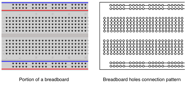
It’s very important to understand that wires that are to be connected together must be plugged into holes in the same group of 5 holes. If you plug a wire into one group, and then another wire into a different group, they are not connected together electrically. If you need more than five things connected together, use wire to connect other sets of five holes to the first set to expand the number of connection points.
As seen in the breadboard above, along the top and bottom of the breadboard are groups of holes running in rows alongside blue and red lines. These are different in that all the holes in one row of holes are connected together. Thus we have four electrical nodes, two along the blue lines and two along the red lines. Normally these are used for power and ground connections and are often referred to as “bus” connections. As a matter of convention, the holes next to the red lines should be used for power, and the ones next to the blue lines should be used for ground.
Schematic Diagrams (Background)
Electronic circuits are drawn using a schematic diagram. These show what types of components are in the circuit and their values, and also shows the interconnections between all the components. With a schematic of a circuit, an engineer has all the information needed to wire up the circuit in the way intended by the person who designed it. However it’s important to remember that a schematic is not a diagram of how the components are physically arranged. The components can be laid out physically in numerous ways.
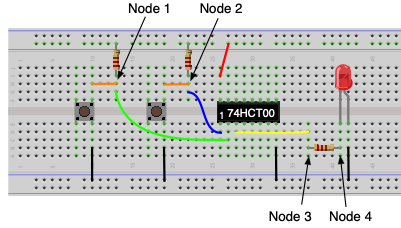
When assembling a circuit on a breadboard, examine the schematic and look for the connection points or nodes where multiple components must be tied together. For example, below is a schematic of a simple circuit with two buttons for input (both with pull-up resistors), a NAND gate, and an LED for output in series with a current limiting resistor.

In this circuit there are four nodes where connection must be made.
- Node 1: The upper switch, its pull-up resistor and an input to the NAND gate.
- Node 2: The lower switch, its pull-up resistor and an input to the NAND gate.
- Node 3: The NAND gate output and the current limiting resistor.
- Node 4: The current limiting resistor and the LED.
Note: For simplicity we haven’t included the additional nodes where connections to ground or power are made in the circuit.
When building this circuit on a breadboard each of these four nodes are implemented by using one of the 5-hole connection blocks as shown below. Plugging all the wires for that node into a single connection blocks established the electrical connection between all the components of the node.
Throughout a circuit each connection point of two more signals will need to use a separate strip of the five breadboard holes to connect them together. As mentioned above, if a point in the circuit requires that more that five signals be connected together, simply use a piece of wire to connect two multiple 5-hole strips together effectively building a larger connection point.
Task 1: Measuring Resistance Using the Digital Multimeter
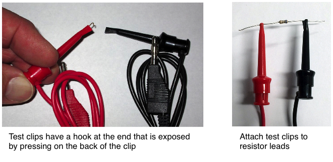
The first task in Lab 1 is use the digital multimeter (DMM) to measure the resistance of some components that are provided in your lab kit. To make the measurements you will need a pair of test leads (one red and one black) to hook the DMM to the component being measured. These can be found on rack in the back right corner of the VHE 205 classroom. The test lead (shown below) has a banana plug on one end that plugs into the receptacle on the front of the DMM. The other end has a hook that is used to attach the test lead to the components as shown on the right below.
Digital Multimeter (Background + Lab Tasks)
The digital multimeter (DMM) is a combination of several instruments and can be used to make a variety of measurements on electrical signals. At a minimum the DMM will have the following basic capabilities.
-
Voltmeter for measuring AC and DC voltages. The voltage level is indicated in volts (V), millivolts (mV = 10-3V) or microvolts (μV = 10-6V).
-
Ammeter for measuring AC and DC current. Current is measured in units of amperes or amps (A), milliamps (mA = 10-3A) or microamps (μA = 10-6A).
-
Ohmmeter for measuring electrical resistance. Electrical resistance is measured in units of ohms (Ω), kilohms (kΩ = 103Ω), or megohms (mΩ = 106Ω).
Depending on how complex the DMM is it may also have other measuring features.
- Frequency meter. The frequency of a time varying signal is measured in cycles per second or Hertz (Hz).
- Capacitance meter. Measures the value of capacitors in microFarads (μF), nanoFarads (nF) or picoFarads (pF).
- Temperture measurements.
- Battery checking.
The Tektronix DMM4020 meters in VHE 205 are capable of making most of the measurements described above. To set up the DMM for this lab experiment, perform the following steps.
-
Turn on the digital multimeter (shown below) by pressing the green button in the lower right corner. If it doesn’t come on, check that it’s plugged in, and that the black power switch on the back is set to “ON”.
-
After it’s done starting up, press the “Ω” button to set it for measuring resistance in Ohms.
-
Plug the two test leads into the “HI” and “LO” input jacks at the far left side of the front panel under the word “INPUT” (red = HI, black = LO). Don’t use the two jacks under the word “SENSE” or the two bottom ones.
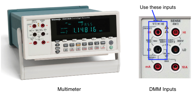
-
The DMM is now ready to measure the resistance of any component connected between the red and black test lead.
Resistor Color Code (Background + Lab Tasks)
Video Introduction - Resistors
In the bag of electronic parts there should be six resistors of three different resistance values. The amount of resistance each has to the flow of electric current is indicated by the color bands around the body of the resistor. In this experiment, we will determine the resistance marked on each resistor and then use the DMM to measure the actual resistance of the resistor.

Resistance values are given in Ohms using a Greek omega character, Ω. For larger values of resistance it can be given in kilo-ohms (kΩ), or mega-ohms (MΩ). The body of the resistor is marked with a series of four color bands (see below) that are used to identify the resistance value. The parts bag should contain two resistors of each of three different resistances (6 total).
Select three resistors from the six provided that have three different sets of colors. To determine the resistor value from the color bands, first figure out which way to read the color bands. One of the bands at the end of the resistor body will be either a silver or gold color indicating the precision of the resistance value (silver = 10%, gold = 5%). The three bands at the other end indicate the value. Starting at the end away from the gold or silver band, the first and second bands are the first and second digits of the resistance value as given by the color codes shown below. The third band is the number of zeros that follow the first two digits. For example, a resistor with yellow, violet and red bands is a 4700 ohm resistor, which we write as 4700Ω or 4.7kΩ.

Make sure you have three resistors with different values (color bands are different) and then do the following:
-
From the color bands determine the resistance of each of the three resistors. Note: You should have resistors of at least 100Ω and less than 2000Ω or 2kΩ.
Important: We will be using these resistors in later parts of this lab. The one with the lowest resistance will be referred to as resistor “R1”, the middle resistance as “R2”, and the one with the highest resistance as “R3”. Record your results on the answer page.
-
If you have not done so, get a pair of test leads from the rack in the back right corner of the classroom, that have banana plugs on one end and test clips on the other end and plug them into the “HI” and “LO” inputs of the DMM.
-
On the front of the multimeter, set it for making resistance measurements by pressing the “Ω” button.
-
In the upper right corner of the DMM display screen it should say “2X4Wire”. If instead it says “4Wire”, press the Ω button again to switch the DMM to 2x4Wire mode.
For each of the three resistors, do the following two steps and record your results on the answer sheet.
-
Connect each of the two test clips to one of the two leads coming from the resistors. Hold the body of the test clip with a couple of fingers and then with your thumb press the back of the test clip to cause the metal hook to extend from the other end of the clip. Resistors are “non-polarized” which means it doesn’t make any difference which resistor lead is connected to the red or black test clip.
-
Once both clips are connected to the resistor leads, the meter should display the resistance in either Ohms, KOhms, or MOhms. The values of the three resistors that you measured should be within about 5% of the component values you determined above by reading the color bands.
Important: Make sure you note what units of resistance are being shown on the meter. For example, if you are measuring a 470Ω resistor, the meter may display 0.470 KΩ. Remember that 0.47 kilohms is the same as 470 Ω.
Question 1:
- What are the values of the resistors R1, R2 and R3 from the color bands?
- What are the values of the resistors R1, R2 and R3 by measuring with the DMM (round to the nearest integer)?
Task 2: Build a Voltage Divider Circuit
The next task for Lab 1 is to build a circuit on the breadboard using two of the resistors you measured above. A voltage source will be connected to the circuit and then you will use the DMM to measure voltages and current in the circuit.
In order to provide power to the circuit and make the necessary measurements you will need a second set of test leads that are different from the ones you used above. From the rack of test leads in the right front corner of the classroom, get two pairs of red and black test leads. These should have a banana plug on one end and a metal pin on the other end (see below).
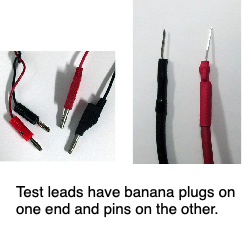
Before building the circuit please read the section below on how to operate the power supply which will be used to provide the voltage source.
DC Power Supply (Background + Lab Tasks)
Video Introduction - Power and Digital Multimeters
Electronic circuits require a power source in order to operate. Electrical power comes in two types: alternating current (AC) in which the voltages varies with time, and direct current (DC) where the voltage is a constant value. The power supplies in VHE 205 (shown below) are triple output variable-voltage DC power supplies meaning that they can simultaneously produce three different DC voltages and that the voltages can be changed by the user. Two of the outputs can produce voltages from zero to 30 Volts with current up to 1.5 Amps. The third output is variable from zero to 6 Volts with current up to 5 Amps. All of these limits are more than any of the requirements we will need in this class, so for all of the lab assignments you can use any of the three channels.
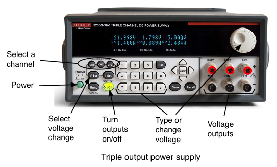
To set up the power supply for this experiment perform the following actions. We recommend you read this whole list of actions before you start performing them so you know what to expect
-
Disconnect any cables from the red and black jacks on the front of the power supply.
-
Press the power switch in the lower left corner to turn it on. The display should light up indicating the voltage settings for the three outputs. Below each voltage reading it should say “<OFF>”. This indicates that while the output may be adjusted for a certain voltage, at this time the output is turned off. This is done to prevent circuits from being burned out in case the output voltage was set by the previous user to some voltage that is incorrect for what it’s now connected to.
-
Press the CH1 button and then the I-Set button so you can adjust the current limit on channel 1. The display should show the maximum amount of current the power supply will provide for the three outputs and the one for channel 1 should be blinking with an underline cursor under one of the digits. If no action is taken to adjust the current within about 4 seconds, the display stops blinking and you’ll have to press the I-Set button again to make an adjustment.
-
Rotate the wheel to the right of the display until the current limit for channel 1 is at least 0.3A. The exact value is not important, it just has to be something around there. If it’s already set to some higher value, you can just leave it there.
-
Press the CH1 button and then the V-Set button so you can adjust the voltage on output channel 1. The display should now show the voltages that are set for the three outputs and the one for channel 1 should be blinking with a underline cursor under one of the digits. If no action is taken to adjust the voltage within about 4 seconds, the display stops blinking and you’ll have to press the V-Set button again to make an adjustment.
-
The wheel to the right of the display is used to adjust the digits above the cursor. The cursor can be moved left or right with the triangular buttons next to the Enter button to make changes to each digit individually. Use the buttons to move the cursor until it is under the tenths of a volt digit, just right of the decimal point. Rotate the knob back and forth and note how the number above the cursor changes but the ones to the right (hundredth and thousandths of a volt) do not change. Also note that if you change the tenths of a volt far enough the number to the left of the decimal point will change accordingly as you move the voltage setting up or down. The voltage setting can be set by changing each digit individually, or by using the knob to change one of the fraction of volt numbers and doing a lot of spinning of the knob until the other digits also are set properly.
-
Use the controls to set the voltage for channel 1 to 3.0 Volts. After you do this the display still shows “<OFF>” for each channel since the outputs have not yet been turned on.
-
Using the test leads you acquired above, plug the red and black banana plugs into the Channel 1 output banana jacks (red to red, black to black.)
The power supply is now ready to provide the voltage source for circuit you will build in the next section, but it is not yet outputing that voltage. To activate the power supply channel to produce the voltage, you must press the green “On/Off” button below the OUTPUT label.
Throughout this lab and ones in the weeks to come, when the instructions say to turn on or off the power supply outputs, do this with the green “On/Off” button below the OUTPUT label. That button controls the power supply outputs but leaves the instrument itself turned on. Don’t turn off the power to the whole power supply with the green POWER button or you will likely lose the settings you have made.
Resistors in Series (Background + Lab Tasks)
Video Introduction - Voltage Dividers
Using the resistor with the smallest resistance as R1, and the one with the middle resistance as R2, build the circuit shown below on the left with the two resistors in series. Resistors are not polarized meaning that they can be connected in a circuit in either orientation. The figure on the right shows how the resistors are placed on the breadboard. The resistor color bands shown are only a representation and the ones on your resistors will likely be different.
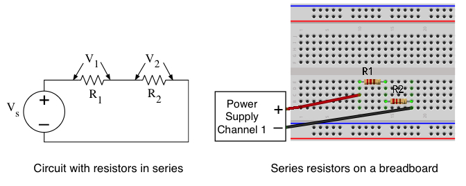
When resistors are connected in series their resistances add together. The total resistance in the circuit is then R = R1 + R2 and by Ohm’s Law the current flowing in the circuit is given by

Since the same amount of current is flowing through both of the resistors, the voltage across each resistor is then

giving the voltage divider equation that was discussed in the lecture.
Using the values of R1 and R2 that you measured with the DMM above, and assuming that Vs has been set to 3V, calculate what the voltage should be across each of the two resistors. Hint: V1 and V2 should add up to Vs = 3V.
Question 2: With VS = 3V, what are the calculated voltages V1 and V2 across resistors R1 and R2?
To test the above results we have to provide the Vs power supply to the circuit.
-
Make sure the power supply outputs are off (“On/Off” button not lit up)
-
If you have not done so, adjust the voltage on channel 1 of the power supply to be 3.0V.
-
Plug the red and black banana plugs of the test leads with the pins on the end into channel 1 of the power supply.
-
Plug the pins on the other ends of the test leads into the breadboard at the points where the positive and negative Vs voltages are to be connected to your circuit as shown above on the right.
-
Turn on the power supply outputs by pressing the green “On/Off” button.
-
Set the DMM to measure DC voltages by pressing the “DC V” button on the DMM.
-
On the DMM, replace the two test leads with clips with the pair that have pins on the ends. These should be inserted into the “HI” and “LO” input jacks at the far left side of the front panel under the word “INPUT”. Don’t use the two jacks under the word “SENSE” or the two bottom ones.
Voltage measurement are made in parallel with the component under test. Your meter is used to measure the change in voltage from one end of the component to the other.
To make this measurement, one test lead from the DMM should be inserted into the same 5-hole connection point as the wire from one end of the resistor, and the other test lead goes to the 5-hole connection point as the wire from the other side of the resistor as shown below. If you make the connections backwards, your multimeter will just show a negative voltage.
Make the connections from the DMM to measure both the V1 and V2 voltages as shown below on the left.
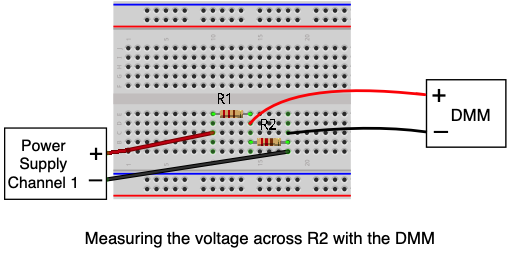
As when you calculated the values using the voltage divider equation, the measured values of V1 and V2 should add up to Vs = 3V.
Question 3: With VS = 3V, what are the measured voltages V1 and V2 across resistors R1 and R2?
Task 3: Measuring Current Through the Circuit
In the previous section you used the DMM to measure the voltage across each of the two resistors. Now we want to use the DMM to measure the the current flowing through the circuit.
Using the results from the previous voltage measurements we can use Ohm’s law to calculate how much current was passing through the resistors. The current will be equal to the voltage (VS) divided by the total resistance which is the sum of R1 and R2. However since the same current is flowing through both resistors, the current is also equal to the voltage you measured across either resistor divided by that resistor’s value.

Question 4: Using the values you just measured for the voltages across R1 and R2, and the values you measured previously for those resistor values, use Ohm’s Law to calculate the current that was passing through each of the resistors. Since the resistors are in series you should get close to the same result for both calculations. In the calculation make sure to use the values for R1 and R2 that you measured with the DMM, not the values from the color bands.
Measuring Current with the DMM
Video Introduction - Measuring Current with the DMM
Note Before proceeding with the steps below, turn off the power supply outputs by pressing the “On/Off” button on the power supply.
Now we’ll measure the current directly with the meter rather than by measuring voltage and using Ohm’s Law. Current measurement are done differently than voltage measurements since the current has to pass through the DMM to be measured. The DMM must be in series with the resistors, not in parallel as above when measuring voltage. Follow the diagram below to hook up the DMM for measuring current.
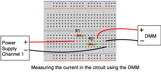
In the diagram above note how we have broken the connection between the power supply and R2. R2 is now connected to the red lead going to the DMM, and black lead of the DMM is connected to the black lead of the power supply by using an additional 5-hole connection block to hook the two together. This change has the effect of placing the DMM in series with the resistors so the current that passes through the resistors also has to go through the meter.
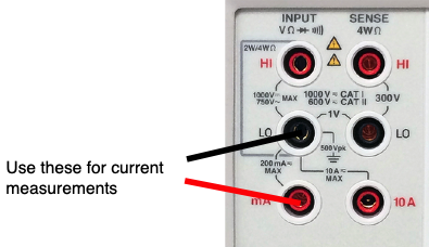
-
If your DMM is still connected to the circuit for measuring voltage disconnect both leads of the meter from the circuit.
-
Turn off the power supply output by pressing the “On/Off” button.
-
On the DMM plug the red lead into the the banana jack that is marked for “mA” as shown above. The black lead should remain plugged into the “LO” jack.
-
Adjust the meter to measure DC current by pressing the button marked “DC I”.
-
Remove the black wire from the power supply from the circuit where it was connected to R2 and move it to some empty connection block as shown above.
-
Connect the red lead from the DMM to R2, and the black lead to the same connection block as where the black lead from the power supply is connected.
-
Turn on the power supply output using the “On/Off” button.
DMM should show how much current is flowing in the circuit. It should be close, but probably not exactly the same as the current value you found above using Ohm’s Law.
Question 5: What was the value that you measured with the DMM in current mode for the current flowing through resistors R1 and R2? The value should be close to what you found for Question 4 by measuring the voltages and using Ohm’s Law.
Task 4: Build a Logic Circuit (Background + Lab Tasks)
Video Introduction - Inverters
As was disussed in the lecture we can use a button as an input to a digital circuit, and use an LED as an output from the circuit. Let’s use these two devices and some digital logic to build a circuit that does something.
We want to make the button turn the LED on when the button is pressed and off when it’s not pressed. From the discussion of how buttons work we know that when the button is pressed it produced a low voltage (logical zero), however the circuit we are building requires a high voltage (logical one) to make current flow through the LED and make it light up.
To make the circuit operate as desired, we need a digital circuit that causes an input of a zero (low voltage) to produce a output of one (high voltage), and vice versa. As we will see in later classes, the action of changing a signal from high to low or low to high is known as a logical inversion. For the inverter operation we’ll use a 74HCT04 integrated circuit which in included in your parts bag.
The schematic diagram for the circuit we will build is shown below. The button on the left (with pull-up resistor) is the input to the inverter, and the LED on the right with a current limiting resistor is the output. Rather that wire up the whole thing and then hope that it will work, we are going to build and test the circuit in stages, not moving on to the next part of the circuit until the first parts are confirmed to be working as expected.
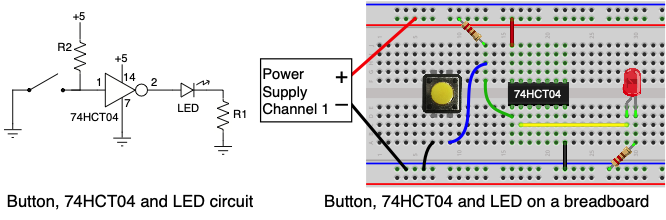
For this part of the lab assignment we will also be using the two “bus strips” on the breadboard to provide connections to power and ground. The circuit requires multiple connections to power and ground and the bus strips provide a convenient place to make as many connections as needed with a minumum amount of wiring.
-
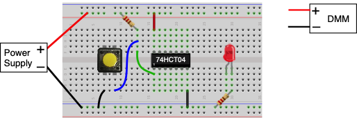
Move the red test lead from the power supply and plug it into any of the holes on the red bus strip.
-
Move the black test lead from the power supply and plug it into any of the holes on the blue bus strip.
This is shown in the figure above. Once you have done that, connections can be made for power and ground from any of the other holes on the bus strips.
Button Input to Circuit
The first part of the circuit is the pushbutton input. The button consists of two electrical contacts, and when the button is pressed it connects them together. When the button is not pressed, the two contacts can have different voltages on them. When the button is pressed, whatever voltage is present on one contact is now on the other contact. We will use the buttons as inputs to digital devices in a way that allows the device to sense whether the button has been pressed or not, and take different actions accordingly.
-
From the parts bag in your project box get one of the small plastic buttons (any color) shown below on the left. On the bottom of the button are four pins that can be inserted into your breadboard.
-
Install the button on the breadboard as shown below on the right. To make the circuit work, the button must be oriented properly when installed on the breadboard. Note that two of the sides of the button each have two metal pins. The button must be installed on the breadboard so these two sides straddle the center channel. Two of the pins should be in holes on one side of the channel, the other two should be in holes on the other side.
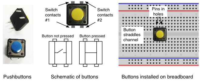
Make sure to press the button firmly into the holes of the breadboard. The black plastic body of the button should be touching the top surface of the breadboard.
-
Cut off a small piece of wire and strip the insulation off both ends using your wire cutters.
-
Insert one end of the wire in one of the ground bus holes (blue bus) and the other into one of the holes below the button as shown below. Make sure the wire is inserted into the same group of holes that the pin from the button is inserted into so they will make an electrical connection. This wire makes the connection from one side of the button to ground.
-
Connect the power supply to the breadboards with the black lead going to the ground bus on the breadboard and the red lead to the power bus as shown.
-
Install the R2 resistor on the breadboard with one end in the +5V bus and the other end in one of the unused 5-hole connection blocks.
-
Take a piece of wire and make a connection between the hole below the button next to the one with the wire going to ground and the connection block where you just put the resistor lead (the blue wire in the figure below). The resistor is now acting as a “pullup resistor” for the button.
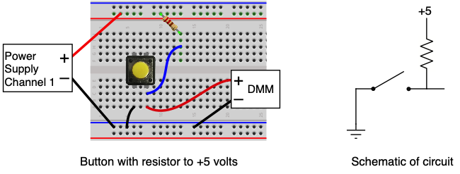
-
Move the red test lead on the DMM back to the inputs used for voltage measurements and press the “DC V” button on the DMM so it is measuring DC volts.
-
Connect the red and black DMM test leads to the breadboard as shown in the diagram above so the DMM is measuring the voltage on the button.
-
Turn on the power supply output with the “On/Off” button.
With the button not pressed the DMM should show about 5.0V since the pullup resistor is pulling the button output up to the power supply voltage. Try pressing the button and the DMM voltage should change. When the button is pressed the DMM should show close to zero volts. With the button is pressed the button output is connected to ground resulting in zero volts on the output.
Important: This is the first part of the logic circuit we are building so it’s important that the button input works correctly as just described. Don’t proceed with the steps below until you have the button producing the correct voltage.
Logic Inverter
The next step is to install the integrated circuit that will perform the logical inversion of the signal from the button. For this you will using a 74HCT04 Hex Inverter IC from your lab kit.
Note: It can be difficult sometimes to read the part number on the top of the integrated circuit, but the inverter IC should say 74HCT04 on top, perhaps with some other numbers and letters there also. If you have problems confirming that it is the 74HCT04 ask an instructor for help.
The 74HCT04 contains six logical inverters that each change an input of zero to a one, and a one to a zero. The IC has 14 pins on it, numbered from 1 to 14. Use the diagram below to locate on the IC the mark or notch that identifies the location of pin 1. Once you have identified pin 1, install the 74HCT04 on your breadboard as shown so that the chip straddles the slot down the center of he board and is oriented so pin 1 is on the side of the slot closest to the blue line. Make sure the 74HCT04 is seated firmly into the holes of the breadboard otherwise its pins will not make solid contact with the breadboard connections.

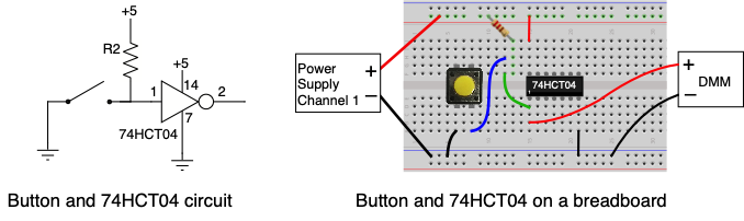
Follow the schematic diagram and picture above to make the following wiring connections.
-
Remove the red wire from the DMM from where it was connected to the button output.
-
Connect pin 14 of the 74HCT04 to the red power bus.
-
Connect pin 7 of the 74HCT04 to the blue ground bus.
-
Connect the input of the inverter (pin 1) to the connection block with the pullup resistor and the button. This is the green wire in the picture above.
-
Connect the DMM’s red wire to pin 1 of the 74HCT04 (the inverter input).
Turn on the power supply outputs and try pressing the button. If it’s wired properly, pressing the button puts a logical zero on the inverter input which will show as zero volts on the DMM. When the button is not pressed the DMM should indicate about 5 volts.
Note: All we have done with the above test is confirm that the button’s output managed to be sent along the wire to the inverter input. This may seem like a trival test but we have to be sure the signal is getting to where it needs to go.
Now move the DMM’s red wire to pin 2 of the 74HCT04, the inverter output, and repeat the test of pressing the button. With the inverter changing the signal, pressing the button should result in about 5 volts on the DMM, and not pressing it should show about zero volts. The signal on pin 2 should be the logic opposite of what is seen on pin 1.
LED for Output
Now that we know that the inverter is providing the correct signal, you can add the last part of the circuit, the LED for the output. You can use any of the three LEDs from your lab kit. Use the R1 resistor for the current limiting resistor.
-
Insert one lead of resistor R1 (the lowest resistance value) into a hole in an unused connection block, and the other end of the resistor R1 goes into a hole in the blue bus (Ground). This will be the LED’s current limiting resistor.
-
Install the LED so the cathode (shorter lead, flat side of case) is in the connection block with resistor R1, and the anode (longer lead, round side of case) is in a different connection block. Don’t worry if you get it backwards. The LED is not going to burn up, it just won’t light up like it should. If that happens, pull it out and try it the other way.
-
Connect the output of the inverter (pin 2) to the anode of the LED (round side). This is the yellow wire in the picture above.
Turn on the power supply output and try pressing the button. If it’s wired properly, pressing the button puts a logical zero on the inverter input, which produces a logical one on the output and that lights up the LED.
Measure Output Voltages and Current
We have studied how Ohm’s Law describes the relationship between resistance and voltage but this law does not apply to devices like the LED. Unlike a resistor where the voltage across it goes up linearly with the amount of current passing through it, an LED has the property that the voltage across the LED is always about the same (around 1.7 to 2.0 volts) for the typical amount of current needed to light up the LED.
When the button is pressed in this circuit the inverter output acts like a voltage source providing a voltage to move current through the LED and light it up. For the 74HCT04 it should produce a logical one output voltage in the 4.5 to 4.8 volt range.
Use the DMM to measure the voltage across the LED (VLED) and the the voltage across the resistor R1 (V1).
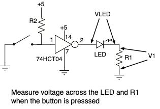
Since you now know the voltage across R1, and we also know the resistance of R1, use Ohm’s Law to calculate how much current must be flowing through both the LED and R1.
Question 6: What are the voltages VLED and V1 across the LED and R1, and how much current is flowing through the LED and R1?
Whoops! It doesn’t seem to be working. Now what do I do?
If a circuit you have built isn’t working, then it’s time to do some debugging. When a circuit doesn’t work it’s probably only one part that isn’t functioning correctly but that makes the whole circuit not work right. When trying to debug a circuit it’s necessary to isolate where the problem is by testing separate parts of the circuit to see if they work or not. Your goal is to figure out what is working and what isn’t, so you can isolate the problem to a subset of the whole circuit. Here are some debugging tips.
-
Use the DMM to make sure the power supply voltage is present on the breadboard and at any point that requires the power supply voltage like the power pin of all the ICs.
-
Make sure the ground connections are installed to the breadboard and to any place on the circuit that should be connected to ground.
-
Use the DMM to test the output of any buttons that are installed. If the pullup resistors have been installed correctly when the button is not pressed that point should be high (logical 1). When the button is pressed it should go to ground.
-
If your circuit uses ICs like the 74HCT00 and 74HCT04, use the meter to confirm they are working. For example find the input voltage to an inverter and then check the output voltage. If it’s working they should be opposite of each other.
-
Just because you installed a wire between two points doesn’t guarantee the signal is getting from one end to the other. The wire may be broken or not making good contact. Test the signal at both ends to make sure the connection is working.
-
Make sure the ICs are plugged fully into the breadboard, and all the pins are in the breadboard holes. When inserting an IC it’s easy to bend a pin so it’s not going into the holes. If this happens and a pin is bent so badly it can’t be straightened, try using one of the other gates on that IC, or get a replacement from the teaching staff.
Results
The answers to the above questions and the review questions below should be added to the “Lab1_Answers.pdf” that can be downloaded from the EE109 web site. That file must be uploaded to Gradescope by the due date. See the Assignments page of the class web site for a link for uploading.
Please make sure to save all the parts used in this lab in your project box. These will be needed for labs throughout the rest of the semester. We suggest also saving all the pieces of wire you cut and stripped since those will be useful in later labs.
Review Questions
Answer the following two question by annotating the “Lab1_Answers.pdf” file available on the class web site. Paper copies of this file are available from the table in front of the VHE 205 podium in case you want to draw it out on paper first before adding it to the file.
Question 1. Below is a schematic diagram for a circuit using a button, 74HCT04 inverter IC, a couple LEDs and some resistors.
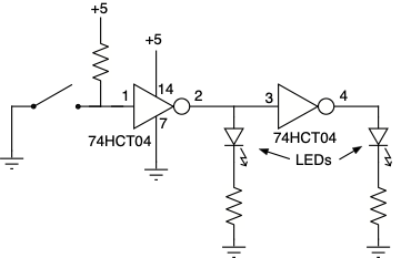
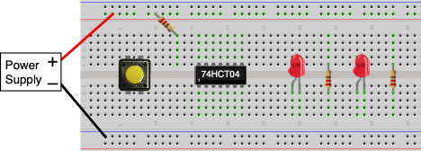
You have been asked to build the circuit on a breadboard. On the picture below of the breadboard, draw in the wiring connections that need to be made to build this circuit. Note: Since it’s hard to tell from the picture below which lead of the LED is for positive or negative you can hook it up either way.
Question 2. The circuit below has been built with a button, inverter and LED. Show what connections need to be made in order to make a current measurement with the DMM of the current passing through the LED.