EE109 – Spring 2023: Introduction to Embedded Systems
Project – Spring 2022
Introduction
This semester's class project is to build an dial-type thermometer that indicates the temperature from both a local and remote temperature sensor. The user can set a temperature threshold and the device will monitor the temperature and provide alerts if the temperature goes above the threshold.
Note: This is a non-trivial project that requires you to not only use the concepts and skills you've learned from past labs but to extend that knowledge and use the higher-level understanding of how embedded systems and microcontrollers work to include use of new components and modules. Getting a full score is not a guarantee. It will require time and intelligent work (not just guess, but verifying on paper and using some of the approaches outlined below). But it is definitely doable. We have broken the project into 3 checkpoints (1 due each week) to help limit the scope of your work to more manageable deliverables. Also, note that while we will still provide help in terms of concept and approach, we will leave it to you to do most of the debugging. When you do need help debugging you should have already used the tools at your disposal: the DMM or scope to verify basic signals are as you expect, LCD print statements to see where your code is executing, whether you are getting into an ISR at all, or what the value of various readings/variables is. Test your code little by little (this is the reason we do checkpoints) and do not implement EVERYTHING and only then try to compile. In addition, when something doesn't work, back out any changes you've made (comment certain portions, etc.) to get to a point where you can indicate what does work and then slowly reintroduce the new changes to see where an issue might lie. If you have not done your own debugging work and just ask for help, we will direct you to go back and perform some of these tasks.
To start, please read the overall project a few times before you even consider thinking about to many details. Get the big picture, hear the terms we use, look for the requirements and/or limitations we specify. Only then consider starting on your project.
For a copy of the project grading sheet, click here.
Thermometer Overview
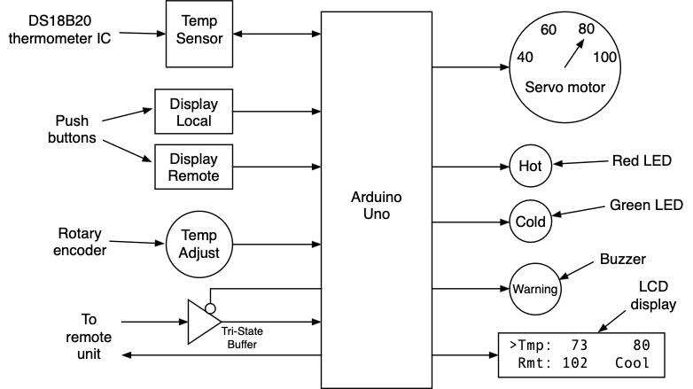
In its simplest form the thermometer measures and shows the temperature on both an LCD display and on a indicator dial where an pointer rotates to point to the current temperature similar to the large thermometer at the east end of the L.A. Coliseum. A block diagram of our thermometer is shown below and it will have the following features.
- A temperature sensor that determines the temperature in the room.
- An LCD display for showing the current temperature in the room, the temperature threshold setting and the temperature received from a remote sensor.
- A servo motor for positioning the pointer to indicate the temperature on a dial.
- A control knob for adjusting the temperature threshold setting.
- Two buttons for selecting whether the dial shows the local or remote temperature.
- Green and red LEDs to indicate that the displayed temperature is below or above the threshold.
- A buzzer for generating an audio alert tone if the temperature is significantly above the threshold.
- A serial interface (RS-232) to another thermometer. Each unit will send its local temperature to the remote unit and receive the remote unit’s temperature.
Operation of the Thermometer
The following is a description of the operation of the thermometer.
- The thermometer is always reading the local room temperature from the temperature sensor IC and displaying the value in degrees Fahrenheit on the LCD with 0.1 degree precision.
- In addition to the temperature being displayed on the LCD, the servo motor is used to rotate a pointer to indicate the current temperature on a dial that shows temperatures from 40 to 100 degrees Fahrenheit. If the temperature goes below 40 degrees, the pointer should point to 40, and if it goes above 100 degrees it should point to 100.
- The rotary encoder is used set a temperature threshold. As the user rotates the knob the temperature threshold should be shown on the LCD display. The threshold can be set to any integer value between 50 and 90 degrees. The software must make sure that the setting are never adjusted to be outside those limits.
- If the temperature in the room is at or below the temperature threshold, the LCD indicates this and the green LED is on constantly. If the temperature is above the threshold but by less than 3 degrees, the LCD shows a warning and the red LED blinks at a 1Hz rate. If the temperature is more than 3 degrees above the threshold, the LCD shows an alert, the red LED is on constantly, and an alert tone is played once for a 0.5 second duration.
- Each time the temperature changes, the temperature value it is transmitted over a serial link to another thermometer. Similarly, your thermometer is receiving remote temperatures from other thermometers when the remote temperature changes. The remote temperature is displayed on the LCD and, if selected, on the temperature dial.
- The two buttons select which temperature, local or remote, are displayed on the indicator dial. The LCD also indicates which temperature is currently being shown on the dial
- The temperature threshold is stored in the Arduino's EEPROM non-volatile memory so the value are retained even if the power is turned off. This makes it unnecessary for the user to set the threshold each time the device is turned on.
- The LCD display should show the following five items but they can arranged in any manner on the screen. They don't have to look exactly like the sample shown above or in the video.
- Current temperature to 0.1 degree precision (e.g. the 73 on the picture above)
- Temperature threshold (integer value) (e.g. the 80 on the picture above)
- Status of temperature in the three ranges. You can say "COOL", "WARM", "HOT" or anything else that conveys the current temperature status.
- The remote temperature received over the serial link (e.g. the 102 on the picture above)
- Indicators as to which temperature is being shown on the indicator dial, the local temperature or the remote temperature.
- The LCD display should always be showing the temperature and threshold settings values even when the threhsold is being adjusted. It should not switch to a separate screen for adjusting the temperature threshold and then switch back when done.
Getting Started
We suggest starting with a copy of your code from Lab 7 since this project uses the rotary encoder. Download from the class web site the file project.zip that contains the files ds18b20.c and ds18b20.h that are needed to work with the DS18B20 temperature sensor that is described below. It also contains the Project_Answers.txt file with information about what needs to be demonstrated to show the project is working.
Most of the components used in this project have been used in previous labs, and your C code from the other labs can be reused if that helps. The project involves the use of three new elements:
- the RS-232 serial module built into the Arduino
- the non-volatile memory (EEPROM) on the Arduino, and
- an external temperature sensor
All three are described below.
Which Port Bits to Use
Since the CPs grading the project may wish to try running the code on their project board, it is very important (and required) that all students use the port connections shown below to connect their buttons, rotary encoder, LEDs, etc. If other port bits are used the project will not operate when the program is run on another board.
| Port Bit | Function |
| PORTB, bit 3 (PB3) | PWM signal to servo motor |
| PORTB, bit 4 (PB4) | Red LED |
| PORTB, bit 5 (PB5) | Green LED |
| PORTC, bit 1 (PC1) | Local display button |
| PORTC, bit 2 (PC2) | Remote display button |
| PORTC, bit 3 (PC3) | 1-Wire bus to DS18B20 |
| PORTC, bit 4 (PC4) | Tri-state buffer enable |
| PORTC, bit 5 (PC5) | Buzzer |
| PORTD, bit 3 (PD3) | Rotary encoder |
| PORTD, bit 2 (PD2) | Rotary encoder |
| PORTD, bit 1 (PD1) | RS-232 Serial Tx output |
| PORTD, bit 0 (PD0) | RS-232 Serial Rx input |
Hardware Construction Tips
The buttons, LEDs, rotary encoder, buzzer and DS18B20, and the various resistors should all be mounted on your breadboard. It's strongly recommended that you try to wire them in a clean and orderly fashion. Don't use long wires that loop all over the place to make connections. You will have about 10 wires going from the Arduino to the breadboard so don't make matters worse by having a rat's nest of other wires running around on the breadboard. Feel free to cut off the leads of the LEDs and resistors so they fit down close to the board when installed.
Make use of the bus strips along each side of the breadboard for your ground and +5V connections. Use the red for power, blue for ground. There should only be one wire for ground and one for +5V coming from your Arduino to the breadboard. All the components that need ground and/or +5V connections on the breadboard should make connections to the bus strips, not wired back to the Arduino.
DS18B20 Temperature Sensor
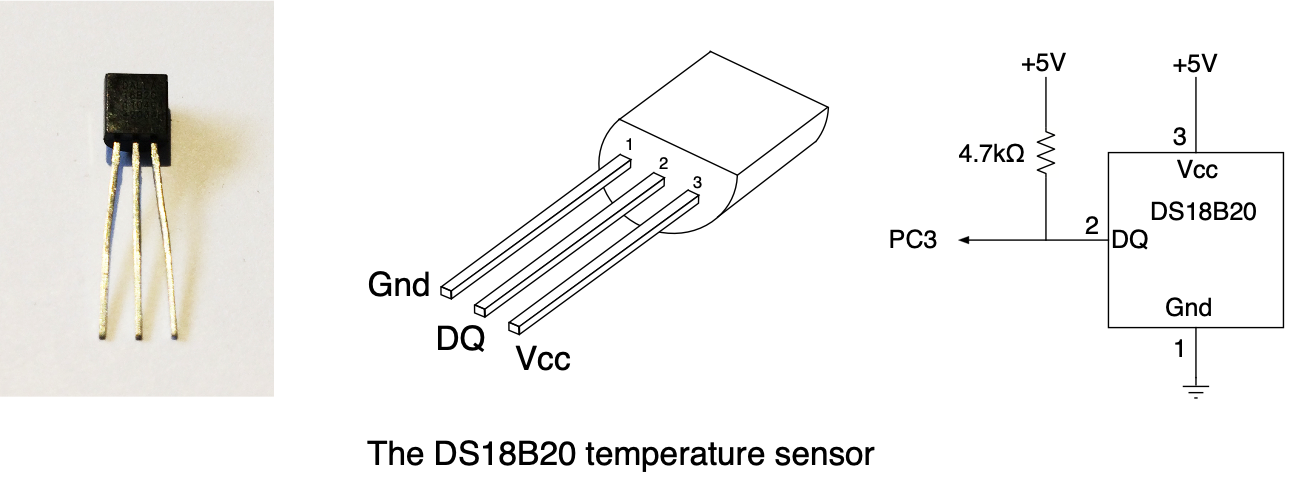
A new component to this project is the DS18B20 temperature sensor. This is an integrated circuit that connects to the microcontroller using a single wire called a "1-Wire" interface by the manufacturer. A picture, pin diagram and schematic diagram of the DS18B20 is shown below. The IC needs to have ground and power connections provided on pins 1 and 3 respectively.
WARNING! Make sure you install the power and ground connections to the DS18B20 correctly and don't reverse them. If the power and ground are reversed the DS18B20 will quickly get very hot and eventually burn out.
The Arduino communicates with the DS18B20 by connecting the "DQ" pin (pin 2) to one of the Arduino's I/O port bits. Note from the schematic that the DQ line must have an external 4.7kΩ pull-up resistor on it. This is not an option, without it the 1-Wire bus will not operate. You can not use the port bit's internal pull-up instead of the external resistor.
From the class web site you can download the files ds18b20.c and ds18b20.h that contains software to communicate with the DS18B20 temperature sensor over the 1-Wire bus. The routines in ds18b20.c assume the DS18B20's "DQ" pin is connected to Port C, pin 3. If you decide to connect it to some other I/O pin, the routines in ds18b20.c will have to be modified to match your configuration.
DS18B20 Application Programming Interface
We've provided some of the routines that do the work necessary for using the DS18B20. The ds18b20.c file contains the following three top-level routines that make up the API (Application Programming Interface) to the sensor.
- ds_init
- Initializes the 1-Wire bus and the DS18B20. The
ds_initroutine only has to be called once at the start of the program. The routine returns 0 if the initialization failed, perhaps due to a defective or missing DS18B20, or more likely due to an error in coding of the functions called by ds_init to communicate with the DS18B20. If the initialization was successful, the routine returns a 1. - ds_convert
- Starts a temperature conversion by the DS18B20. The
ds_convertroutine has to be called each time you want to acquire a new temperature sample. The call tods_convertstarts the conversion but returns before the conversion has completed. - ds_temp
- The
ds_temproutine must be called to acquire the temperature data. The function is called with one argument, the name of aunsigned chararray of length 2. If it is called prior to the conversion completing, it will return a value of zero. If the conversion has completed, it returns a value of 1, and the two data bytes containing the temperature data are placed in the two element array. The format of the temperature data stored in the array is described below.
The ds18b20.h file contains declarations for these three three functions and can be included in your program file to declare the functions.
char ds_init(void);
void ds_convert(void);
char ds_temp(unsigned char *);
Below is a sample of some code that uses these routines to read the temperature data.
#include "ds18b20.h"

main()
{
    unsigned char t[2];

    if (ds_init() == 0) {    // Initialize the DS18B20
         // Sensor not responding
    }

    ds_convert();    // Start first temperature conversion

    while (1) {
        if (ds_temp(t)) {    // True if conversion complete
            /*
              Process the values returned in t[0]
              and t[1] to find the temperature.
            */

            ds_convert();   // Start next conversion
        }
    }
}
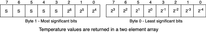
The temperature data is returned in two elements of the char array that is passed to the ds_temp function. Element 0 of the array contains the eight least significant bits. Bits 3, 2, 1 and 0 are the fractional part of the temperature value. Element 1 of the array contains the four most significant bits of the temperature value. The result is essentially a 12-bit 2's complement number stored in two 8-bit bytes with the sign ('S' in the diagram below) extended to fill it out to a 16-bit 2's complement number. The two bytes together represent the temperature in degrees Celsius times 16. For example if the temperature is 27.5 degrees Celsius, 16 times this is 44010, or 0x01B8 in hex. The two values in the array elements would then be 0x01 in element 1 and 0xB8 in element 0.
DS18B20 Low-Level Functions
The three API high-level routines described above make use of several low-level routines in ds18b20.c that are not intended to be seen or used by a user of the API. These routines do the actual work of communicating with the DS18B20 to acquire the temperature data.
- ds_reset
- Send a reset pulse to the DS18B20. This routine is provided for you.
- ds_writebyte
- Send one 8-bit byte to the DS18B20. This routine is provided for you.
- ds_readbyte
- Read one 8-bit byte from the DS18B20. This routine is provided for you.
- ds_write1bit
- Send a 1 bit to the DS18B20. This routine you will have to write.
- ds_write0bit
- Send a 0 bit to the DS18B20. This routine you will have to write.
- ds_readbit
- Read a single bit from the DS18B20. This routine you will have to write.
The code for most of the above routines is provided in the ds18b20.c file but you will have to write the code for the ds_write0bit, ds_write1bit and ds_readbit routines.
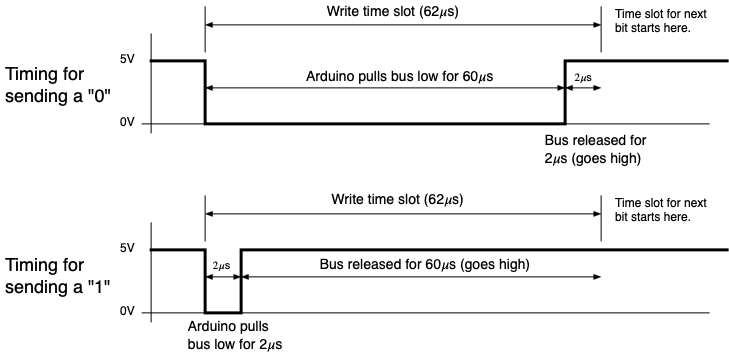
The Arduino sends bits to, and receives bits from, the temperature sensor (the DS18B20) by signaling over the 1-Wire bus. Unlike RS-232 where there are separate sending and receiving connections between two devices, the 1-Wire bus uses a single wire that is used to send data from the Arduino to the DS18B20, and at other times from the DS18B20 to the Arduino.
Signaling on a 1-Wire bus is based on the idea that both devices connected to the bus allow the bus to "float", also called "releasing the bus", by not putting any signal on the bus. A pull-up resistor connected to the bus then pulls the bus to the high state and it sits in the high state when neither device is trying to send any information. When one device needs to send data to the other it sends 0's and 1's by putting a zero volts signal on the bus for different lengths of time and letting it float the rest of the time. The receiving device notes how long the bus was in the 0 volts state and from that determines whether a 0 or 1 was being sent to it.
The diagram below shows the timing for sending a 0 bit and a 1 bit from the Arduino to the DS18B20.
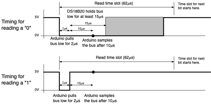
Reading bits is done in a similar fashion. The Arduino signals the DS18B20 to send bits by pulling the bus down to 0v for short time and then releasing it to go high. It then monitors the bus to see if the other device pulls the bus low (sending a 0) or leaves it high (sending a 1). This can be done by simply reading the state of the bit in the PIN register after the specified amount of time has gone by.
The diagram below shows the timing for reading a 0 and 1 bit sent from the DS18B20 to the Arduino.
The operations of pulling the 1-Wire bus down to zero volts or letting it float can be done by just changing the value of the DDR bit for that I/O port bit. If the PORT bit is 0 and the DDR is 0 making it an input, the I/O pin floats and the pull-up resistor will make the bus go to the high state. If the PORT bit is 0 and the DDR bit is 1, then the I/O pin becomes a output. The zero in the PORT bit will make the I/O pin pull the bus down to zero volts.
The DS18B20 datasheet describes the timing for writing ones and zeros, and for reading a bit from the DS18B20 in more detail on pages 15-17. You should refer to these pages when completing the code for the these routines.
Temperature Calculations
The DS18B20 converts the temperature into a two's complement 12-bit value (8-bits for the integer portion and a 4-bit fractional portion) representing the temperature in degrees Celsius, and stores these in two bytes that can be transferred from the DS18B20 by your program. The DS18B20 datasheet on pages 5 and 6 describes the format of how the temperature data is stored, and includes several examples of how values are represented.
Your program should convert these two bytes to an Fahrenheit value. The Fahrenheit value to be displayed should include one digit to the right of the decimal point (e.g. 74.6). The bits for the fractional part of a degree Celsius that are included in the data returned from the DS18B20 must be properly factored into the conversion to the Fahrenheit temperature. In other words, don't throw away any of the precision of the sampled value. Use all of it to give the most accurate Fahrenheit value possible for displaying (to one decimal place).
Hint: The ds_temp routine returns the temperature in two bytes. Combine these two 8-bit values into a single 16-bit signed variable before doing any operations to convert it to Fahrenheit.
Converting from Celsius temperature to Fahrenheit is usually done with the formula

however in this project all temperature calculations must be done in integer (fixed point) arithmetic. Do NOT use any floating point numbers (float or double) either as constants (e.g. 0.1) or variables.
Watch this video for more tips on doing floating point operations using integers. The slides are available here.
When using integer arithmetic, and variables with a limited numeric range, it's easy to go wrong. For example if we do the following
    unsigned char c, f;
    f = (9 / 5) * c + 32;
the integer division of "9 / 5" will be 1 and give result of "F = C + 32". On the other hand, if we do it as
    unsigned char c, f;
    f = (9 * c) /  5 + 32;
The product "9 * c" will probably give a result outside the range of the unsigned char variable and result in an overflow. To get the correct answer, you must do the conversion using variables of the right size and do the calculations in the proper order.
Reminder: Any use of Floating Point variables OR *constants* will result in large deductions in the visual grading
Temperature Comparisons
While the temperature should be displayed to a 1/10 of a degree precision, you can do your temperature comparisons for turning LEDs on and off using just the integer portion of the temperature. You don't have to do any rounding to get the integer values, simply drop the fractional part of the temperature. Similarly, the temperature settings done with the rotary encoder (and stored in the EEPROM) are only done to integer values.
Servo Motor Indicator Dial
Besides displaying the temperature on the LCD, the temperature is also shown on a round dial by using a servo motor to rotate an indicator to point to the temperature. The servo is controlled by Timer/Counter2 since this is the only timer with an output signal that is not blocked by the LCD panel. Servos normally operate with PWM signals with a period of 20ms, but with Timer2 the longest period that can be achieved is 16.4ms and the servos will work properly with this period PWM signal.
The width of the PWM pulse must vary between 0.75ms and 2.25ms. Assuming Timer2 is using the largest prescalar so as to have the maximum period, use that to determine the values that must go in the OCR2A register for the minimum pulse width of 0.75ms, and the value for the maximum pulse width of 2.25ms. Note: The calculation of these numbers was done in review question 2 of Lab 9.
Once you have determined the two OCR2A values for the minimum and maximum pulse width, you can use those to develop an equation to map the temperature values to servo positions. The number that goes in the OCR2A register has a linear relationship with the temperature value. Linear equations are based on two points, and you have the two points:
- The maximum OCR2A value will cause the motor to rotate fully to the left and point at the 40 degree position: (40, max OCR2A)
- The minimum OCR2A value will cause the motor to rotate fully to the right and point at the 100 degree position: (100, min OCR2A)
Using these two points, determine a linear equation for mapping the temperature values to the OCR2A values. Once you have figured out the equation, write code to implement it, but remember to only use fixed point variables and operations. Do not use floating point operations or variables. Make sure the calculations to not result in overflows of the fixed point variables.
Every time the temperature to be displayed changes, a new value for OCR2A should be calculated using the equation you developed above and stored in that register.
Reminder: Any use of Floating Point variables OR *constants* will result in large deductions in the visual grading
Local/Remote Selector Buttons
The thermometer has two buttons for selecting which of two temperatures to display on the temperature dial, the one that is measured on your project board (the local temperature) or a temperature received over the serial link (see below) from another thermometer (the remote temperature).
- If the Local button is pressed to place the thermometer in local display mode, the temperature that is measured locally on the project board is displayed on the temperature dial.
- If the Remote button is pressed to place the thermometer in remote display mode, the temperature that is received over the serial link from another thermometer is displayed on the temperature dial.
When the display mode is changed, the thermometer should show the most recent temperature from the local or remote device. For example, if the mode is changed to "Remote", the dial should immediately rotate to the last received remote temperature. It should not wait until the next remote temperature is received since there is no telling how long that will be.
It is strongly recommended that you use the Pin Change Interrupts to implement the detection of a button press. This makes the code much simpler than doing it by polling.
The selected mode must be indicated in some way on the LCD screen. The recommended way is to put a character of some type next to the local or remote temperature that is shown on the LCD.
The thermometer should be be in the Local mode when it is powered on or reset. It should stay in the selected mode until the other button is pressed to switch the mode. The user does not have to hold the button down to make it stay in either the local or remote mode.
Temperature Threshold, LEDs and Buzzer
The rotary encoder is used to set a temperature threshold from 50 degrees to 90 degrees as an integer value. As the user rotates the knob the temperature threshold should be shown on the LCD display. The software must ensure that the setting is never adjusted to be outside those limits. Whenever a new threshold value is set, it is stored in the non-volatile EEPROM (see below).
The temperature threshold value and the current temperature are continuously compared to determine which of the LEDs to turn on. When doing the comparison, only the integer part of the local temperature need be used, the fractional part can be ignored.
- If the local temperature is less than or equal to the threshold temperature, the green LED should be on, and the LCD should show an alert like "OK", or "COOL" or something similar.
- If the local temperature is greater than the threshold temperature, but less then 3 degrees above the threshold, the red LED should blink at a 1Hz rate (see below), and the LCD shows a "WARM" warning.
- If the local temperature is 3 degrees or more above the threshold temperature, the red LED should be on constantly, the LCD should show "HOT", and the buzzer (see below) should sound the alert tone one time. The buzzer need only sound once for each time the temperature reaches the "HOT" range.
Blinking the LED
The blinking of the LED in the "WARM" state should be done using Timer/Counter1 to implement a 0.5 second delay. Do not use the delay functions to make the LED blink. Each time TIMER1 interrupts, your code can change the state of the LED output signal. With a half second delay between interrupts this will have the effect of making the LED blink at a 1Hz rate. When the state of the thermometer changes from the "WARM" state to one of the others, the code should turn off TIMER1 and also turn off the LED.
Buzzer
In Lab 7 you worked with producing tones of different frequencies from the buzzer. Those tones were done with code that used delays of half the desired output period between operations to make the output signal go high or low. The result was a squarewave signal at the desired frequency.
The problem with this method is that the program is locked into the delay routines while they measure out the selected delay time. A better way to create the tones is by using a timer to generate interrupts at the desired rate. Timer/Counter0, an 8-bit timer, should be used to generate a one half second tone of whatever frequency you choose. When the program wants to sound the buzzer it can start the timer running. Each time an interrupt occurs the ISR changes the state of the output bit driving the buzzer. After the required number of transitions have occured, the ISR can shut the timer off to end the output. Do not use the delay functions to drive the buzzer.
Serial Interface
Here is a video lecture/tutorial from previous semesters' labs that describes the operation of RS-232 serial and to the slides that accompany it.
The serial interface between thermometer devices will use an RS-232 link to send the temperature data between the units. The serial input and output of the Arduino uses voltages in the range of 0 to +5 volts. These are usually called ``TTL compatible'' signal levels since this range was standardized in the transistor-transistor logic (TTL) family of integrated circuits. Normally for RS-232 communications these voltages must be converted to positive and negative RS-232 voltages levels in order for it to be compatible with another RS-232 device. However for this project we will skip using the voltage converters and simply connect the TTL level signals between the project boards.
Locating the RX and TX signals
The Ardunio's transmitted (TX) and received (RX) data appears at two places on the LCD shield as shown in the figure below. The black connector along the top of the LCD shield has two holes marked "TX" and "RX" that can be used by inserting wires into these holes as has been done in previous labs. Alternatively, you can attach the wire jumpers to the D1 pin for the TX signal, or the D0 pin for RX signal.
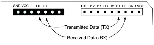
For the RX and TX signals, there is no advantage or difference in using one connection point over the other. The D1 pin is connected to "TX", and D0 pin is connected to "RX" on the LCD board so you can use either one.
Tri-State Buffer to Eliminate Contention on RX Line
When using the the serial signals to communicate with another device there is an issue with programming the Arduino that needs to be resolved. If the received data coming from another Arduino (or the TX data being looped back) is connected directly to the RX input (Arduino port D0) it creates a conflict with a signal used to program the Arduino’s microcontroller. Both the RX data and the programming hardware try to put an active logic level on the D0 input and this can prevent the programming from succeeding. When this happens you will get error messages like these.
  avrdude: stk500_recv(): programmer is not responding
  avrdude: stk500_getsync() attempt 1 of 10: not in sync: resp=0x00
  avrdude: stk500_recv(): programmer is not responding
  avrdude: stk500_getsync() attempt 2 of 10: not in sync: resp=0x00
The solution for this is to use a tri-state gate to isolate the incoming data from the RX input until after the programming is finished. The gate you will using is a 74HCT125 that contains four non-inverting tri-state buffers (see below).
Each of the four buffers have one input, one output and an enable input that controls the buffer’s tri-state output. In the diagram below on the left, the enable inputs are the connections going to the little circles on the side of the gate. The circle indicates that it is an "active low enable", meaning that the gate is enabled when the enable input is a logical 0. In that state, it simply copies the input logic level to the output (0 → 0, 1 → 1). However when the gate is disabled (enable input = 1) its output is in the tri-state or hi-Z state regardless of the input. In that condition, the gate output has no effect on any other signal also attached to the output.
The serial communications circuit needs to include the 74HCT125 tri-state buffer in the path of the received data as shown below. The received data from the other Arduino should go to one of the buffer inputs, and the output of the buffer should be connected to the RX port of the Arduino. Remember to also connect pin 14 of the 74HCT125 to +5V, and pin 7 to ground.
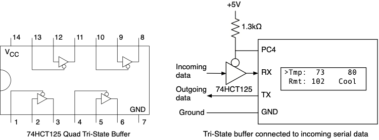
The tri-state buffer's enable signal is connected to a digital I/O port bit. For this project, use I/O port bit PC4 (Port C, bit 4) to control the tri-state buffer. When the Arduino is being programmed all the I/O lines become inputs. With no signal coming from the Arduino, the pull-up resistor will cause the PC4 line go high and put a logic one on the tri-state buffer’s enable line. This disables the output (puts it in the hi-Z state) and the programming can take place. Once your program starts, all you have to do is make that I/O line an output and put a zero in the corresponding PORT bit. This will make the enable line a logical zero, that enables the buffer, and now the received data will pass through the buffer to the RX serial port.
Note that the tri-state buffer and pull-up resistor is necessary even if you have configured the Arduino and project board to use a loopback where the transmitted data from the TX port is connected to the RX port. The TX and RX being connected together will interfere with the programming if the tri-state buffer is not used. The TX data must be connected to the buffer input so the it can be isolated from the RX port until the programming is completed.
Format of the Serial Signals
For all the thermometers to be capable of communicating with others, use the following parameters for the USART0 module in the Arduino. Refer to the slides from the lecture on serial interfaces for information on how to configure the USART0 module for these settings.
- Baud rate = 9600
- Asynchronous operation
- Eight data bits
- No parity
- One stop bit
Serial Interface Protocol
The serial data link between two thermometers uses a simple protocol:
- Data sent using ASCII characters for easier debugging
- Accommodates varying sizes of temperature text strings
- Allows the system to recover from errors such as a partially transmitted or garbled data packet
In many devices that use serial links these features are implemented using relatively complex data structures and interrupt service routines so the processor does not have to spend much time doing polling of the receiver and transmitter. We'll do it in a simpler manner that should work fine for this application.
The protocol for communicating the measured temperature between two thermometers will consist of a string of up to six bytes in this order:
- The start of the string is indicated by the '@' character.
- A plus or minus sign ('+' or '-').
- Up to three ASCII digits (’0’ through ’9’) representing the temperature in degrees Fahrenheit as an integer value (no fractional degrees). You device should only send the necessary digits. For example if the temperature is 68 degrees, you only need to send 68. You should not send 068.
- After all characters for the temperature have been sent the end of the temperature data string is indicated by sending the ’#’ character.
For example, to send a temperature of 78 degrees, the transmission should consist of @+78#.
Transmitting Data
When your software determines that the local temperature has changed, it should call a routine that sends the characters for the temperature data to the remote unit. The serial link is much slower than the processor so the program has to poll the transmitter to see when it can put the next character to be sent in the transmitter’s data register for sending. The UCSR0A register contains a bit (UDRE0 - USART Data Register Empty) that tells when it’s ready to be given the next character to send. While this bit is a zero, the transmitter is busy sending a previous character and the program must wait for it to become a one. Once the UDRE0 bit becomes a one, the program can store the next character to be sent in the UDR0 register.
    while ((UCSR0A & (1 << UDRE0) == 0) { }
    UDR0 = next_character;
While your program is waiting for all the characters to be transmitted it should still respond to interrupts from modules with interrupts enabled, but it does not have to reflect any changes on the display until after all the data has been sent and it’s back in the main program loop.
Receiving Data
Receiving the temperature data from the remote unit is a bit more complicated since you have no idea when the remote unit will send the data. One simple way to implement this is to have your program check for a received character each time through the main loop. If one has been received, then call a function that waits for the rest of the characters and when complete displays the temperature on the LCD. Unfortunately this method of receiving characters has one very bad design flaw in it. If for some reason the string is incomplete, maybe only the first half of the string was sent, the device will sit in the receiver subroutine forever waiting for the rest of the data and the ’#’ that marks the end of the transmission.
A better solution, and one that should be implemented in your program, is to use interrupts for the received data. Receiver interrupts are enabled by setting the RXCIE0 bit to a one in the UCSR0B register. When a character is received the hardware executes the ISR with the vector name “USART_RX_vect”.
For reading the incoming temperature data, each time a character is received, an interrupt is generated and the ISR determines what to do with the character. After all the characters have been received, the ISR sets a global variable to indicate that a complete remote temperature value has been received and is available. When the main part of the program sees this variable has been set, it gets the value and displays it. By using the interrupts, the program is never stuck waiting for a character that might never come.
It is also important to consider all the possible errors that might occur in the transmission of the date, such as missing start (’@’) character, missing or corrupted temperature characters, missing end (’#’) character, etc. The software must make sure all of these situations are handled cleanly and don’t leave the device in an inoperable state.
To handle possible errors in the received data, the thermostat should operate on the principle that if an error of any kind is detected in the data being received, it discards the current remote temperature data that it was in the midst of receiving and goes back to waiting for the next temperature data to start coming in. It does not have to notify the main program that an error was encountered, or try to correct the error, or guess what the correct data was. Simply throw it away and go back to waiting for a new data packet.
To implement this, use the following variables to properly receive the data:
- A 5 byte buffer for storing the data from the remote sensor as it comes in (the 4 data bytes and a ’\0’ byte, at the end.)
- A global variable to act as a data started flag that tells whether or not the start character (’@’) has been received indicating data is to follow.
- A variable that tells how many data characters have been received and been stored in the buffer so far. This also tells the ISR where in the buffer it should store the next character.
- A global variable to act as a data valid flag to indicate that the '#' has been received and the buffer contains a valid temperature string. This variable should be zero while receiving the temperature data, and set to one only after receiving the ’#’ that marks the end of the sequence.
If the ISR receives a ’@’, this indicates the start of a new temperature data sequence even if the previous sequence was incomplete. Set the data start variable to a one, and clear buffer count to 0. Also set the the valid data flag to zero to indicate that you now have incomplete data in the buffer. This sets up the ISR to wait for the next transmission.
For the next characters that arrive, your code must check to see if they are valid.
- If the ISR receives a ‘+’ or ‘-’, and it’s not first character after the ’@’, something has gone wrong so reset the data started flag to zero to discard this packet.
- After that, if something other than the number 0 through 9 or the end of transmission marker ’#’ is received, reset the data started flag to zero to discard what has been received so far. This will set up the ISR to wait for the next transmission.
- If a sequence has started and a correct character is received, store it in the next buffer position and increment the buffer count. Your code should also make sure there is room in the buffer for the data. If the data tries to overrun the length of the buffer this would imply two transmissions have somehow been corrupted into looking like one, and in this case you should set the data started flag back to zero to discard this transmission.
- If the ISR receives a '#', and the buffer count is greater than zero (meaning the sequence has started) set the valid data flag variable to a one to indicate complete data in the buffer. However if the end transmission character is received but there is no temperature data (nothing in the buffer between the ’@’ and the '#', the flag variable should not be set to a one.
The main program can check the data valid variable each time through the main loop. When it sees it has been set to a one, it can call a function to convert the temperature data from from a string of ASCII characters to a fixed-point binary number (see below). It should probably also clear the data valid variable to a zero so it doesn’t re-read the same data the next time through the loop.
Using sscanf to Convert Numbers
In Lab 5 you learned how to use the "snprintf" function to convert a binary number into a string of ASCII characters. Now we need to go the other way, from a string of ASCII characaters into single binary fixed-point number. For this we can use the "sscanf" function that is part of the the standard C library.
Important: As with using snprintf, in order to use sscanf you must have the following line at the top of the program with the other #include statements.
#include <stdio.h>
The sscanf function is called in the following manner
sscanf(buffer, format, arg1, arg2, arg3, ...);
where the arguments are
- buffer
- A char array containing the items to be converted to binary values.
- format
- The heart of the sscanf function is a character string containing formatting codes that tell the function exactly how you want it to convert the characters it finds in input string. More on this below.
- arguments
- After the format argument comes zero or more pointers to where the converted values are to be stored. For every formatting code that appears in the format argument, there must be a corresponding argument containing the a pointer to where to store the converted value.
The format argument tells sscanf how to format the output string and has a vast number of different formatting codes that can be used. The codes all start with a percent sign and for now we will only be working with one of them:
- %d
- Used to format decimal integer numbers. When this appears in the format string, the characters in the input string will be interpreted as representing a decimal integer number, and they will be converted to the corresponding binary value. The result will be stored in the variable that the corresponding argument points to.
The format string must have the same number of formatting codes as there are arguments that follow it in the function call. Each formatting code tells how to convert something in the input string into its corresponding argument. The first code tells how to convert something that is stored where "arg1" points, the second code is for "arg2", etc.
Example: Assume you have a char array containing the characters representing three numbers. The code below would convert them into the three int variables.
    char buf[] = "12 543 865";
    int num1, num2, num3;
    sscanf(buf, "%d %d %d", &num1, &num2, &num3);
The arguments are pointers to where the three values are to be stored by using the form "&num1" which makes the argument a pointer to num1 rather than the value of num1. After the function has executed, the variables "num1", "num2" and "num3" will contain the binary values 12, 543 and 865.
Important: The "%d" formatting code tells sscanf that the corresponding argument is a pointer to an int variable. When it converts the characters to a binary value it will store it in the correct number of bytes for that variable type. If you wish to store a value in a "short", or a "char" variable, you must modify the format code. The formatting code "%hd" tells it to store a 2 byte short, and "%hhd" tells it to store a 1 byte char.
Here’s the above example but modified to use three different variable types.
    char buf[] = "12 543 865"; char num1;
    short num2;
    int num3;
    sscanf(buf, "%hhd %hd %d", &num1, &num2, &num3);
Non-volatile EEPROM Memory
The ATmega328P microcontroller contains 1024 bytes of memory that retains its data when the power is removed from the chip. It's similar to the FLASH memory where your program is stored but intended to be written to and read from your program rather than just during the "make flash" operation. In this project we will be using the EEPROM to store the temperature threshold value. In this way when the device is turned on it will have the same setting as it had previously.
The avr-gcc software includes several routines that you can use for accessing the EEPROM. To use these functions, your program must have this "include" statement at the beginning of the file that uses the routines.
#include <avr/eeprom.h>
The two routines that you should use for your program are described below.
- eeprom_read_byte
- This function reads one bytes from the EEPROM at the address specified and returns the 8-bit value. It takes one argument, the the EEPROM address (0-1023) to read from. For example to read a byte from EEPROM address 100:
unsigned char x;
x = eeprom_read_byte((void *) 100);
- eeprom_update_byte
- This function writes one byte to the EEPROM at the address specified. It takes two arguments, the address to write to and the 8-bit value of the byte to be stored there. For example to write the byte 0x47 to address 200 in the EEPROM:
eeprom_update_byte((void *) 200, 0x47);
Your code should use the above routines to store the temperature threshold in the EEPROM whenever it has been changed. You can assume the threshold will always be in the range of 50 to 90 degrees. The number can be stored in an 8-bit variable and only requires writing a single "unsigned char" variable to the EEPROM. You can choose any address in the EEPROM address range (0 to 1023) to store the value. When your program starts up it should read the value from the EEPROM, but it must then test the value to see if it is a valid threshold value. If the EEPROM has never been programmed, it contains all 0xFF values. If you read the EEPROM data and the value is not in the range 50 to 90, then your program should ignore this number and revert to using a default threshold value that is defined in your source code.
Warning! The EEPROM on the microcontroller can be written to about 100,000 times and after that it will probably stop working. This limit should be well beyond anything we need for this project but it's very important that you make sure you don't have the above EEPROM writing routines in some sort of loop that might go out of control and do 100,000 writes before you realize the program isn't working right.
Software Issues
Multiple Source Code Files
Your software should be designed in a way that makes testing the components of the project easy and efficient. In previous labs we worked on putting all the LCD routines in a separate file and this practice should be continued here. Consider having a separate file for the encoder routines and its ISR. The serial interface routines and ISR can be in another file. Code to handle the two buttons and the two LEDs can either be in separate files or in the main program since there isn't much code for these. All separate code files must be listed on the OBJECTS line of the Makefile to make sure everything gets linked together properly.
Accessing Global Variables
In the project you may need to use global variables that are accessed in multiple source files. A global variable can be used in multiple files but it must be defined in one place. We define variables with lines like
    char a, b;
    int x, y;
Global variables must be defined outside of any function, such as at the start of a file before any of the functions (like "main()"). Variables can only be defined once since when a function is defined, the compiler allocates space for the variable and you can't have a variable stored in multiple places.
If you want to use that global variable in another source code file, the compiler needs to be told about that variable when compiling the other file. You can't put another definition of the variable in the file for the reason given above. Instead we use a variable declaration. The declaration of a global variable (one that's defined in a different file) is done using the "extern" keyword. The "extern" declaration tells the compiler the name of the variable and what type it is but does not cause any space to be allocated when doing the compilation of the file.
For example, let's say the global variable "result" is accessed in two files, project.c and stuff.c, and you decide to define it in the project.c file. The project.c file would contain the line defining the variable
int result;
and the stuff.c file would need to have the line
extern int result;
declaring it in order to use the variable. If the "extern" keyword was omitted, both files would compile correctly, but when they are linked together to create one executable, you would get an error about "result" being multiply defined.
If you have global variables that need to be accessed in multiple files it's recommended that you put the declarations in a ".h" file that can be included in all the places where they may be needed. For the example above, create a "project.h" file that contains the line
extern int result;
and then in both project.c and stuff.c add the line
#include "project.h"
It doesn't cause problems to have the declaration of a variable, like from an ".h" file, included in the file that also contains the definition of the same variable. The compiler knows how to handle this correctly.
Improving Your Makefile
In class we discussed how the "make" program uses the data in the "Makefile" various modules that make up a program. This project may require several source code files, some with accompanying ".h" header files, so the generic Makefile should be modified to describe this. For example, let's say you have five C files for the project and five header files:
- The main program is in
project.cand has some global variables and functions declared inproject.h - The LCD routines are in
lcd.cwith global declarations inlcd.h - The functions to handle the rotary encoder are in
encoder.cwith global declarations inencoder.h - The functions to handle the serial interfac are in
serial.cwith global declarations inserial.h - The functions to handle the DS18B20 are in
ds18b20.cwith global declarations inds18b20.h
Let's also say that project.h is "included" in the encoder.c file, and the header files for the LCD, encoder, serial and DS18B20 routines are included in the project.c file. In this situation, the following lines should be added to the Makefile after the "all: main.hex" and before the ".c.o" line as shown below.
all:    main.hex

project.o:   project.c project.h lcd.h encoder.h serial.h ds18B20.h
encoder.o:   encoder.c encoder.h project.h
serial.o:    serial.c serial.h
ds18b20.o:   ds18b20.c ds18b20.h
lcd.o:       lcd.c lcd.h

.c.o
Adding all the dependencies to the Makefile will make sure that any time a file is edited, all the affected files will be recompiled the next time you type make.
Building Your Design
It's important that you test the hardware and software components individually before expecting them to all work together. Here's a one possible plan for putting it together and testing it.
The project should be built in three stages with it checked off at each of the three stages.
For checkpoint 1:
- Install the LCD shield and write code to put a splash screen on the LCD. This will confirm that you can write messages on both lines of the display. Use your file of LCD routines from the previous labs to implement this.
- Edit the
ds18b20.cfile to finish the three routines that were left for you to complete. - Install the DS18B20 thermometer IC. Write code that uses the provided routines to initialize the IC and then read the temperature from it. At first you can display the two bytes of temperature data as four hex digits (using the %x format string placeholder in an snprintf function call. Put this code in a loop so it continuously read the temperature and displays it on the LCD. Is the displayed value about what you would expect to see? Try heating up the DS18B20 but pressing your figure on it, or cool it by blowing on it, and confirm that the temperature changes.
- Once you know the sensor is returning valid data, implement the code to convert the Celsius temperature to Fahrenheit and display it on the LCD with one digit to the right of the decimal point.
- Demo the operation of this functionality to a TA to get the credit for Checkpoint 1
For checkpoint 2:
- Add the servo motor. Write code to convert the measured temperature to the value to generate the correct PWM pulse.
- Install the rotary encoder. Define the temperature threshold variable and use your encoder routines from Lab 7 to change this number up and down. Display the number on the LCD. Add code to make sure the number stays between 50 and 90 degrees.
- Install the LEDs. Add code to control the LEDs based on the measured temperature and the temperature threshold. Also have it write the associated message on the LCD depending on which range it is in.
- Write code to use TIMER1 to implement the blinking of the red LED when in the "WARM" range.
- Write code to use TIMER0 to generate the tone on the buzzer, and to play the tone whenever the temperature goes into the "HOT" range.
- Add code to save the temperature threshold in the EEPROM whenever it has been changed, and to read the value from the EEPROM when the program starts up. Check that value is within 50 to 90.
For checkpoint 3:
- Install the 74HCT125 tri-state buffer. Write code to enable the the buffer after the program starts. Check that you can program the Arduino with the serial connections in place. This means the tri-state buffer is doing what it is supposed to do.
- Write test code that continually sends data out the serial interface and use the oscilloscope to examine the output signal from the D1 port of the Arduino (transmitted data). For 9600 baud, the width of each bit should be 1/9600 sec. or 104μsec.
- Write code to send the temperature value out the serial interface in the format specified above and check with the scope that it’s being transmitted after the temperature changes. Check that the transmitted packet matches the specified protocol with the start and end characters present.
- Write code to receive the temperature and display it on the LCD. This also should be done without using any floating point routines.
- Do a "loopback" test of your serial interface. Connect the D1 (TX) pin to the input pin on the 74HCT125 so you are sending data to yourself. Try heating and cooling your sensor and see if the remote temperature is the same as the one you displayed on the LCD as the local temperature.
- Install the two buttons. Write code to read the button presses. Use of the Pin Change Interrupts is recommended. Add code to indicate on the LCD which mode, "Local" or "Remote" the thermometer is currently in. Note that since we have separate buttons for the two modes we only need to detect that the button was pressed. We don't have to deal with debouncing or having delays when sensing that a button is down.
- Add code so the servo motor is positioning the dial based on whether the thermometer is in the "Local" or "Remote" mode.
- Demo the operation of this (and the Checkpoint 1 and 2) functionality to a TA to get the credit for Checkpoint 3
Results
Getting your project checked off can be done in multiple checkpoints to ensure you earn partial credit for parts that are working. At each checkpoint we will confirm operation of all the features from the previous checkpoints plus the new features added in the current checkpoint.
Checkpoint 1:
- Splash screen with your name shown at start.
- Temperature sensor working and displaying temperature in degrees Fahrenheit on the LCD.
Checkpoint 2:
Demonstrate items from the previous checkpoint. Then demonstrate:
- Servo motor positions pointer to correct position for the measured temperature.
- Rotary encoder can adjust temperature threshold.
- Threshold stored in EEPROM and retrieved when Arduino restarted (power cycled).
- Red and green LEDs operate correctly including blinking.
- Buzzer sounds warning if temperature too high
Checkpoint 3:
Demonstrate items from the previous checkpoint. Then further show:
- Serial interface can transmit local temperature to remote thermometer.
- Serial interface can receive remote temperature and display on LCD.
- Buttons can select which temperature to show on the servo's dial.
Review Questions
Be sure to answer the two review questions in Project_Answers.txt and reprinted below:
- Cost Analysis: Assume we are building 1000 units of this system. Use the provided part numbers (see the webpage) and the digikey.com or jameco.com website to find the total cost per unit (again assume we build a quantity of 1000 units) for these thermometers. Itemize the part costs (list each part and its unit cost when bought in units of 1000) and then show the final cost per unit below. Note: You only need to price the components used in the project (not all the components in your lab kit. Also, you do not need to account for the cost of the circuit board or wires. In a real environment we would manufacture a PCB (Printed Circuit Board). As an optional task, you can search online for PCB manufacturers and what the costs and options are in creating a PCB.
- Reliability, Health, Safety: Assume this system was to be sold to consumers for use at their home.
- What scenarios might you suggest testing (considering both HW and SW) before releasing the product for use?
- How might you make your design more reliable? By reliability we don't just mean keeping it running correctly (though you should consider that), but also how you can detect that a connected component has failed to gracefully handle such situations. You can consider both HW and SW points of failure, issues related to the operational environment, etc. and how to mitigate those cases.
Submission
Make sure to comment your code with enough information to convey your approach and intentions. Try to organize your code in a coherent fashion.
The Project_Answers.txt file and all source code (all .c and .h files and the Makefile) must be uploaded to the Vocareum web site by the due date. Make sure you have included all files since the graders may download your submission, compile it on their computer and download it to their board for checking the operation. See the Assignments page of the class web site for a link for uploading.
Please make sure to save all the parts used in this lab in your project box. All the contents of the project box and components will need to be returned at the end the semester.