EE109 – Spring 2023: Introduction to Embedded Systems
Project – Fall 2021
Introduction
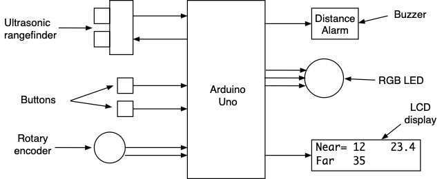
This semester's class project is to build a device that measures the range to an object by using an ultrasonic rangefinder and displays the range on an LCD. The rangefinder will have the following features.
- An ultrasonic rangefinder for measuring distances up to 400cm.
- Buttons to initiate a range measurement and set distance thresholds.
- An LCD display for showing the measured range. The display is also used for setting the distance thresholds.
- A control knob for setting the near and far distance thresholds.
- A multicolor LED for showing how the measured distance compares to a pair of range thresholds.
- A buzzer for playing an alarm tone if he distance is less than the near threshold.
For a copy of the project grading sheet, click here
Operation of the Rangefinder
The operation of the rangefinder is relatively simple.
- Each time the "Acquire" button is pressed a signal is sent to the ultrasonic sensor to initiate a range measurement by sending out an ultrasonic pulse.
- As the sensor makes a range measurement, it sends to the Arduino a 0→1→0 pulse that varies in width proportional to the range to the object that reflected the ultrasonic pulse. The Arduino monitors the received pulse watching for the initial rising edge and the falling edge at the end of the pulse to determine the length of the pulse. Once this is known it performs the calculations to find the corresponding distance.
- Whenever a range measuring event has completed, the unit displays the distance in centimeters with one decimal place (e.g. "27.6") on the LCD display.
- The multicolor LED is used to show how the range measurement compares to the two range thresholds that were set by the rotary encoder.
- If the range is less than the near threshold, the LED is red.
- If the range is greater than the far threshold, the LED is green.
- If the range is between the near and far thresholds, the color of the LED is varied so that it goes from red at the near threshold to green at the far threshold.
- If the range exceeded the rangefinder maximum range (400cm), the LED is blue.
- When a range is below the near threshold, in addition to the LED being red, the buzzer sounds a one second alarm tone.
- An "Threshold" button is used to determine which of two range thresholds are adjusted by the rotary encoder, either a near threshold or a far threshold. Each time the button is pressed the mode toggles from one mode to the other and the mode the unit is currently in is indicated on the LCD.
- If the user turns the rotary encoder knob, the selected range threshold number is changed up or down and displayed on the LCD. This number is an integer value and can change from 1 to 400 cm. The near and far thresholds must always be at least 5cm apart.
- Whenever either range threshold is changed, the new value is stored in the Arduino's EEPROM non-volatile memory so the values are retained even if the power is turned off. Whenever the rangefinder is turned on or restarted, the threshold values are read from the EEPROM memory making it unnecessary for the user to set the distance thresholds each time the device is turned on.
To see a short video demonstrating the operation of the rangefinder, click here.
Getting Started
We suggest starting with a copy of your code from Lab 7 since this project uses the rotary encoder. Download from the class web site the file project.zip that contains the Project_Answers.txt file with information about what needs to be demonstrated to show the project is working.
Most of the components used in this project have been used in previous labs, and your C code from the other labs can be reused if that helps. The buzzer was used in Lab 6 (ADC) and you can use some of that code to play a tone on the buzzer. The rotary encoder is the same as in Lab 7. You should use the encoder code that uses interrupts rather than polling. The timers were used in Lab 8. The project involves the use of three new elements, the ultrasonic rangefinder, non-volatile memory (EEPROM) and an a three color LED. These are described below.
Which Port Bits to Use
Since the operation of the project may have to be confirmed by running the code on one of the instructor's project boards, it is very important (and required) that all students use the port connections shown below to connect their rangefinder, buttons, rotary encoder, LED, etc. If other port bits are used the project will not operate when the program is run on another board.
| Port Bit | Function |
| PORTB, bit 3 (PB3) | RGB LED's green segment |
| PORTB, bit 4 (PB4) | Button to acquire a range measurement |
| PORTC, bit 1 (PC1) | Rotary encoder |
| PORTC, bit 2 (PC2) | Rotary encoder |
| PORTC, bit 3 (PC3) | Button to toggle near/far range threshold |
| PORTC, bit 4 (PC4) | RGB LED's blue segment |
| PORTC, bit 5 (PC5) | Buzzer |
| PORTD, bit 2 (PD2) | Rangefinder trigger |
| PORTD, bit 3 (PD3) | Rangefinder output |
Hardware Construction Tips
The rangefind, buttons, LED, rotary encoder, buzzer, ICs, and the various resistors should all be mounted on your breadboard. It's strongly recommended that you try to wire them in a clean and orderly fashion. Don't use long wires that loop all over the place to make connections. You will have about 10 wires going from the Arduino to the breadboard so don't make matters worse by having a rat's nest of other wires running around on the breadboard. Feel free to cut off the leads of the LEDs and resistors so they fit down close to the board when installed.
Make use of the bus strips along each side of the breadboard for your ground and +5V connections. Use the red for power, blue for ground. There should only be one wire for ground and one for +5V coming from your Arduino to the breadboard. All the components that need ground and/or +5V connections on the breadboard should make connections to the bus strips, not wired back to the Arduino.
Ultrasonic Range Sensor
The range sensor is a single module that can be mounted on your breadboard. It requires +5V power and ground, and two digital signals. One signal is an output from the Arduino and is used to initiate a range measurement. The other signal is an input to the Arduino and is the pulse generated by the sensor to indicate the range.
A copy of the manufacturer's datasheet for the sensor can be viewed with this link.
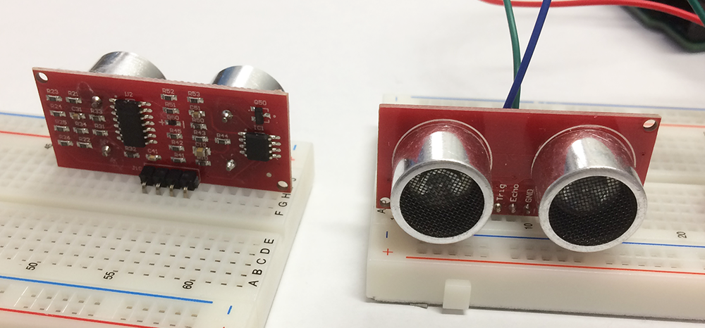
The four pins at the bottom of the sensor should be installed in four separate blocks of holes on the breadboard. The purpose of each pin is shown on the front of the sensor: VCC, Trig, Echo, GND. The trigger (output) and echo (input) signals are digital signals so those can be interfaced to the digital I/O port bits of the Arduino. Read the datasheet for information on the format of these signals.
Determining the Sensor Pulse Width
The pulse that comes back from the sensor can be connected to a I/O port bit that has the Pin Change Interrupt enabled. The ISR will be invoked once on the rising edge of the pulse (start of the measurement) and again on the falling edge (end of the measurement).
The ISR can control one of the timers to produce a count of how many counter clock cycles it took to get from the rising edge to the falling edge. For determining the width of the measurement pulse from the sensor, it is recommended that you use the 16-bit TIMER1 to count at a known frequency. At the start of the program the timer can be configured but left in the stopped state (all prescaler bit cleared to zeros). When the ISR is invoked by the start of the pulse, the timer's count can be set to zero with the statement
TCNT1 = 0;
and then the timer is started by loading the correct prescalar bits.
When the ISR is invoked again by the end of the pulse, the timer can be stopped by setting the prescalar bits to all zeros and the value in the count registered can be examined.
pulse_count = TCNT1;
Since the rate at which the timer was counting is known, the count value can be used to determine how long the pulse was in the high state.
In order get the most accurate distance values you want to have the counter operating at as fast a frequency as possible. From the manufacturer's datasheet you can determine what could be the longest time possible between the start and end of the pulse. You should select a counter prescalar that allows the count to go as high as possible before that time is reached but still can be represented by an unsigned 16-bit number.
Note: You are NOT using this timer as you did in the stopwatch lab where you generated an interrupt at a fixed interval and then update a software variable count. Instead, you will start the timer (hardware counter) and let it count freely until you get back the echo and then stop the timer and read it's current count from the TCNT1 register. You will lose points if you try to use the timer in the same style as the stopwatch lab.
Time-out Function on Pulse Width Measurement
We want our rangefinder to be robust and not subject to problems that may be caused by electrical noise spikes on the signal lines. For example, a noise spike on the sensor output may be incorrectly taken to be the start of a measurement pulse, but the Arduino may then sit there forever waiting for the falling edge of the pulse. To prevent this from happening we want to install a "watch dog timer" function that will prevent the rangefinder from getting locked up.
The manufacturer's datasheet tells what the maximum range is for the sensor. From that we can calculate what the highest count value is that we would ever see from our TIMER1 if it's operating properly. If the TIMER1 count ever goes above this value, we can assume that something has gone wrong and we want to abandon this measurement. You should set up your TIMER1 so that it generates an interrupt if this maximum count value is reached. The ISR can then stop the timer and reset whatever is needed to discard this measurement and wait for a new measurement to be initiated.
Multicolor LED
A new component for this assignment is a multicolor LED. The LED contains three separate LED elements inside it, one glows red, one glows green and the third glows blue, which leads to them being called "RGB LEDs". The three LEDs inside it have separate anode (higher voltage) leads, but the their cathode leads, the one that goes to lower voltage or ground, connected together so it is a referred to as a "common cathode" device. RGB LEDs can also be purchased with separate cathode leads and a "common anode". On the package, the common cathode lead can be identified since it is longer than the other three. When wiring up an RGB LED, all three elements need to have separate current limiting resistors as shown below.
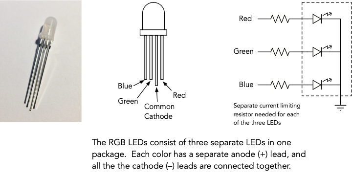
It is recommended that you use the 680Ω resistors from your parts bag for the red and green LEDs, and use one of the 1.3kΩ resistors for the blue LED.
For this project the three colors are used as follows.
- The red element glows if the range is less than the near threshold.
- The green element glows if the range is more than the far threshold.
- The blue element glows if the range was not acquired since it exceeded the maximum measurable range of 400cm.
- For ranges between the near and far threshold, the brightness of the red and green elements will be controlled by a pulse width modulation (PWM) signal that will make the LED go from all red at the near threshold, to 50% red and 50% green (which should appear yellow) at the midway point between the thresholds, to all green at the far threshold. See the section below for more information on the PWM signal.
The PWM signal doesn't actually change the brightness of the LED when it's on, but by turning it on and off rapidly it can be made to appear dimmer or brighter. In this project we will be using a single PWM signal generated by TIMER2. The PWM signal directly controls the green LED while an inverted version controls the red LED. This will have the effect of making one LED get dimmer as the other gets brighter.
The blue LED is controlled by a separate signal from Port C, bit 4 (PC4). When the blue LED is on, both the green and red LEDs should be off. The green LED can be turned off by reducing the PWM pulse width to the minimum value but this then causes the red LED to be on most of the time. For this reason we need to add some logic to turn off the red LED when the blue LED is turned on. The truth table below describes the situation.
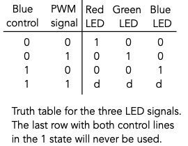
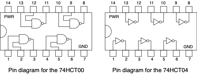
As stated above, and as shown in the table, the PWM signal can control the green LED, and the blue control can control the blue LED. The red LED is not controlled directly by the Arduino. It is controlled by a signal derived from the PWM and blue LED signals according to the truth table shown above. For the red LED you will need to design the circuit that generates the red LED signal with inputs from the PWM signal and the blue control signal. The 74HCT00 quad 2-input NAND gate IC, and the 74HCT04 hex inverter IC (pin diagrams below) should be used to build this circuit for controlling the red LED.
Pulse Width Moduation
A pulse width modulation or PWM signal is a binary periodic signal that has a fixed period, but the amount of time the signal spends in the 1 state is varied. The width of the part of the period where the signal is high is varied or "modulated".
The timing diagram below shows three PWM signals with the same period but with three different pulse widths: 10%, 50% and 80%.
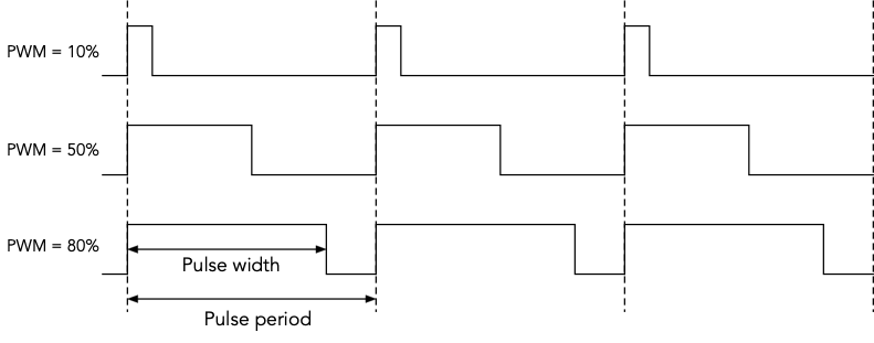
If an LED were attached to these signals, the LED would be the same brightness for all the times the signals were in the high state. However our eye tends to integrate the high and low parts of the signal over many pulse periods so we would see it as dim for the 10% signal, and it would appear bright for the 80% signal.
Generating a PWM Signal
Important: See the slides on pulse width modulation for information on how to configure the timers to generate PWM signals.
All three timers in the Arduino microcontroller can generate PWM signals that can be output on various pins. Due to the presence of the LCD panel and the I/O signals it uses, only TIMER2 has a PWM output pin that is available for our use. The PWM signal can appear on the "OC2A" output, which is same pin as Port B, bit 3 (PB3).
The configuration of TIMER2 needs to do the following
- Refer to Table 18-8. Configure the timer for "Fast PWM" mode with "TOP" equal to 0xff by putting the correct values in the WGM22, WGM21 and WGM20 bits. This means the counter will count from 0 to 0xff (255) and then repeat. The WGM22 bit is in register TCCR2B (section 18.11.2) and the WGM21 and WGM20 bits are in register TCCR2A (section 18.11.1).
- Refer to Table 18-3. Configure the timer so the PWM signal appears on the OC2A output and is in non-inverting mode by putting the correct values in the COM2A1 and COM2A0 bits in the TCCR2A register. This means the OC2A output will be set to a 1 at the start of the pulse period and then be cleared to a 0 when the counter matches the width value you put in the OCR2A register.
- Refer to Table 18-9. Configure the prescalar for divide by 256 operation by putting the correct values in the CS22, CS21 and CS20 bits in the TCCR2B register. This gives a counter clock period of 16μs, and with 256 counts per PWM period the PWM signal will have a period of 4.1ms.
- Load the OCR2A register with some value like 128 so the timer will be outputting a 50% duty cycle PWM signal to start.
- The OC2A output from the TIMER2 module is shared with the Port B, bit 3 I/O signal. In order to make OC2A an output, set the PB3 bit in DDRB to a one so it can be an output for the PWM signal.
Once these steps have been done in the program you should be able to view the PWM signal on PB3 with an oscilloscope.
Determining the Width of the PWM Pulse
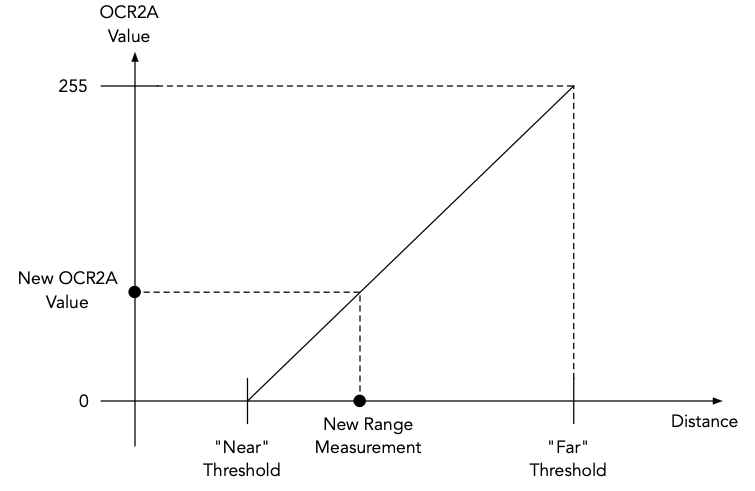
Every time there is a distance measurement, if the distance is between the near and far thresholds, a new PWM pulse width value should be calculated and stored in the OCR2A register to adjust the PWM signal. This can be done with a linear equation based on two known points. At a distance of the "near" setting the OCR2A value should be 0. At a distance of the "far" setting the OCR2A value should be 255. Your code should use this to determine the correct OCR2A value for the new distance and load it into the register.
Use the truth table above to generate the Red and Green outputs given the Arduino blue control and PWM output. As an example, setting the OCR2A value to 0 should make the PWM signal essentially zero the for the whole period which will turn off the green LED and turn the red LED on to full brightness. Conversely, setting OCR2A to 255 makes the signal a 1 for whole period turning the green LED on to full brightness and turning the red LED off.
Buzzer
In Lab 7 you worked with producing tones of different frequencies from the buzzer.
Those tones were done with code that used delays of half the desired output period between operations to make the output signal go high or low. The result was a squarewave signal at the desired frequency.
The problem with this method is that the program is locked into the delay routines while they measure out the selected delay time. A better way to create the tones is by using a timer to generate interrupts at the desired rate, and when each interrupt occurs the ISR changes the state of the output bit driving the buzzer. Your buzzer should generate a one second tone of whatever frequency you choose.
To receive full credit for the buzzer output generation, use TIMER0, one of the two 8-bit timers, to generate the buzzer signal. If you use the delay routines as in Lab 7, you will still receive partial credit for this task.
Non-volatile EEPROM Memory
The ATmega328P microcontroller contains 1024 bytes of memory that retains its data when the power is removed from the chip. It's similar to the FLASH memory where your program is stored but intended to be written to and read from your program rather than just during the "make flash" operation. In this project we will be using the EEPROM to store the two range threshold values. In this way when the device is turned on it will have the same settings as it had previously.
The avr-gcc software includes several routines that you can use for accessing the EEPROM. To use these functions, your program must have this "include" statement at the beginning of the file that uses the routines.
#include <avr/eeprom.h>
The two routines that you should use for your program are described below.
- eeprom_read_word
- This function reads two bytes from the EEPROM starting at the address specified and returns the 16-bit value. It takes one argument, the the EEPROM address (0-1023) to read from. For example to read a word from EEPROM address 100:
short x;
x = eeprom_read_word((void *) 100);
- eeprom_update_word
- This function writes two bytes to the EEPROM starting at the address specified. It takes two arguments, the address to write to and the 16-bit value of the word to be stored there. For example to write the word 0x2f47 to address 200 in the EEPROM:
eeprom_update_word((void *) 200, 0x2f47);
Your code should use the above routines to store the range thresholds in the EEPROM whenever they have been changed. You can assume the threshold will always be in the range of 1 to 400 cm. These numbers can be stored in an 16-bit "short" variable and only requires writing a single "short" variable to the EEPROM for each value. You can choose any addresses in the EEPROM address range (0 to 1022) to store the values. When your program starts up it should read the value from the EEPROM, but it must then test the value to see if it is a valid threshold value. If the EEPROM has never been programmed, it contains all 0xFF values. If you read the EEPROM data and the value is not in the range 1 to 400, then your program should ignore this number and revert to using a default threshold value that is defined in your source code.
Warning! The EEPROM on the microcontroller can be written to about 100,000 times and after that it will probably stop working. This limit should be well beyond anything we need for this project but it's very important that you make sure you don't have the above EEPROM writing routines in some sort of loop that might go out of control and do 100,000 writes before you realize the program isn't working right.
Software Issues
Multiple Source Code Files
Your software should be designed in a way that makes testing the components of the project easy and efficient. In previous labs we worked on putting all the LCD routines in a separate file and this practice should be continued here. Consider having a separate file for the encoder routines and its ISR. Code to handle the rangefinder, the two buttons the serial interface and the LED can either be in separate files or in the main program. All separate code files must be listed on the OBJECTS line of the Makefile to make sure everything gets linked together properly.
Accessing Global Variables
In the project you may need to use global variables that are accessed in multiple source files. A global variable can be used in multiple files but it must be defined in one place. We define variables with lines like
    char a, b;
    int x, y;
Global variables must be defined outside of any function, such as at the start of a file before any of the functions (like "main()"). Variables can only be defined once since when a function is defined, the compiler allocates space for the variable and you can't have a variable stored in multiple places.
If you want to use that global variable in another source code file, the compiler needs to be told about that variable when compiling the other file. You can't put another definition of the variable in the file for the reason given above. Instead we use a variable declaration. The declaration of a global variable (one that's defined in a different file) is done using the "extern" keyword. The "extern" declaration tells the compiler the name of the variable and what type it is but does not cause any space to be allocated when doing the compilation of the file.
For example, let's say the global variable "result" is accessed in two files, project.c and stuff.c, and you decide to define it in the project.c file. The project.c file would contain the line defining the variable
int result;
and the stuff.c file would need to have the line
extern int result;
declaring it in order to use the variable. If the "extern" keyword was omitted, both files would compile correctly, but when they are linked together to create one executable, you would get an error about "result" being multiply defined.
If you have global variables that need to be accessed in multiple files it's recommended that you put the declarations in a ".h" file that can be included in all the places where they may be needed. For the example above, create a "project.h" file that contains the line
extern int result;
and then in both project.c and stuff.c add the line
#include "project.h"
It doesn't cause problems to have the declaration of a variable, like from an ".h" file, included in the file that also contains the definition of the same variable. The compiler knows how to handle this correctly.
Improving Your Makefile
In class we discussed how the "make" program uses the data in the "Makefile" various modules that make up a program. This project may require several source code files, some with accompanying ".h" header files, so the generic Makefile should be modified to describe this. For example, let's say you have four C files for the project and four header files:
- The main program is in
project.cand has some global variables and functions declared inproject.h - The LCD routines are in
lcd.cwith global declarations inlcd.h - The functions to handle the rotary encoder are in
encoder.cwith global declarations inencoder.h - The functions to handle the rangefinder are in
rangefinder.cwith global declarations inrangefinder.h
Let's also say that project.h is "included" in both the encoder.c and rangefinder.c files, and the header files for the LCD, encoder and rangefinder routines are included in the project.c file. In this situation, the following lines should be added to the Makefile after the "all: main.hex" and before the ".c.o" line as shown below.
all:    main.hex

project.o:   project.c project.h lcd.h encoder.h rangefinder.h
encoder.o:   encoder.c encoder.h project.h
rangefinder.o: rangefinder.c rangefinder.h project.h
lcd.o:       lcd.c lcd.h

.c.o
Adding all the dependencies to the Makefile will make sure that any time a file is edited, all the affected files will be recompiled the next time you type make.
Building Your Design
It's important that you test the hardware and software components individually before expecting them to all work together. Here's a one possible plan for putting it together and testing it.
- Install the "Acquire" button on the board and add code to detect the "Acquire" button pressed. When the Acquire button is pressed generate a pulse on the port bit that will be connected to the
Trigsignal to the sensor. Check with the scope that the pulse is generated and is of the correct length. - Add the range sensor to the board and connect the
TrigandEcholines to the Arduino digital I/O port bits. Put two channels of the scope on theTrigandEcholines and observe what happens when the Acquire button is pressed. The sensor should produce a pulse in response to the trigger signal. Try holding your hand in front of the sensor and see if you can make the echo pulse width change by moving your hand farther and closer to the sensor as you trigger it. - Determine how to configure TIMER1 to use it to measure the width of the pulse. You need to pick a prescaler value that will make it run as fast as possible so as get the most accurate timing of the pulse width. However it must run at a speed where the count will still be less than the maximum 16-bit value (65,535) if the sensor returns the maximum width output pulse.
- Write code to implement the Pin Change Interrupt ISR for the sensor output signal. This ISR needs to do different things depending on whether it's detecting the start of the pulse (zero timer count, start timer) or the end of the pulse (stop timer, set flag that measurement complete). For debugging, have the count value printed on the LCD and see if it changes as you make measurements at differing distances.
- Convert the count value from the timer to the distance in millimeters that you will need later to display the distance with one decimal place, and then to distance in centimeters for comparing to the two thresholds. This should be done without using any floating point arithmetic. Write the distance value to the LCD after each range measurement is completed.
- Check that your measurement calculation correctly handles distance greater than the specified maximum range by indicating on the LCD that the distance is too far.
- Add the "Threshold" button to the the board and add code to detect when it has been pressed. Each time it's pressed it toggles the adjustment mode between near and far, and this should be indicated on the LCD.
- Install the rotary encoder on the board and add code to use the rotary encoder to set the range threshold values. It should adjust the threshold that has been selected by the "Threshold" button and show the value on the LCD. Check that this allows you to adjust both values between 1 and 400 cm, but they should always be separated by at least 5cm.
- Write code to store the minimum distance values in the EEPROM, and read the EEPROM values when the program starts. Confirm that this is working by adjusting the distance values and cycling the power on the project. It should start up and display the distances you had set before. Make sure to add code that checks that the distances you loaded from the EEPROM are valid values.
- Install the RGB LED on the board and add code to light up the segments based on the near and far range threshold and the distance that has been measured.
- Add the code to sound the buzzer. Use some of your code from the ADC lab to play a tone for a short time (1 second or less). Make the tone play whenever the distance is below the near range threshold.
Results
Getting your project checked off can be done in multiple checkpoints to ensure you earn partial credit for parts that are working. At each checkpoint we will confirm operation of all the features from the previous checkpoints plus the new features added in the current checkpoint.
Checkpoint 1:
- Splash screen with your name shown at start.
- Acquire button initiates a range measurement.
- Rangefinder measures range to object and shows the distance on the LCD with 0.1 cm precision
Checkpoint 2:
Demonstrate items from the previous checkpoint. Then demonstrate:
- Button selects which distance threshold to adjust and indicate selection on on the LCD.
- Rotary encoder can adjust both thresholds.
- Range is limited to between 1 and 400, and near and far thresholds are always 5cm apart.
- Threshold settings stored in EEPROM and retrieved when Arduino restarted (power cycled).
Checkpoint 3:
Demonstrate items from the previous checkpoint. Then further show:
- The LED is red if the range is less than the near threshold.
- The LED is green if the range is more than the far threshold.
- The LED is blue if the range was beyond 400cm.
- The LED changes color from red to green as range changes from the near to the far threshold
- Buzzer sounds if range is below the near threshold.
Review Questions
Be sure to answer the two review questions in Project_Answers.txt and reprinted below:
- Cost Analysis: Assume we are building 1000 units of this system. Use the provided part numbers (see the webpage) and the digikey.com or jameco.com website to find the total cost per unit (again assume we build a quantity of 1000 units) for these range finding systems. Itemize the part costs (list each part and its unit cost when bought in units of 1000) and then show the final cost per unit below. Note: You only need to price the components used in the project (not all the components in your lab kit. Also, you do not need to account for the cost of the circuit board or wires. In a real environment we would manufacture a PCB (Printed Circuit Board). As an optional task, you can search online for PCB manufacturers and what the costs and options are in creating a PCB.
- Reliability, Health, Safety: Assume this system was to be used in a real industrial monitoring application.
- What scenarios might you suggest testing (considering both HW and SW) before releasing the product for use?
- How might you make your design more reliable? By reliability we don't just mean keeping it running correctly (though you should consider that), but also how you can detect that a connected component has failed to gracefully handle such situations. You can consider both HW and SW points of failure, issues related to the operational environment, etc. and how to mitigate those cases.
Submission
Make sure to comment your code with enough information to convey your approach and intentions. Try to organize your code in a coherent fashion.
The Project_Answers.txt file and all source code (all .c and .h files and the Makefile) must be uploaded to the Vocareum web site by the due date. Make sure you have included all files since the graders may download your submission, compile it on their computer and download it to their board for checking the operation. See the Assignments page of the class web site for a link for uploading.
Please make sure to save all the parts used in this lab in your project box. All the contents of the project box and components will need to be returned at the end the semester.