EE109 – Spring 2023: Introduction to Embedded Systems
Lab 8
Pulse Width Modulation
Honor Statement
This is an individual assignment. The code you write, use for the demo and submit should be wholly your own and not produced by working in teams or using, in part or in whole, code written by someone else (found online, from a fellow student, acquaintance, etc.). You will be asked to verify this when you submit your code on Vocareum by signing your name in the honor.txt file on Vocareum. Penalties for violation include a 0 on the assignment and a potential further deduction or referral to Student Judicial Affairs.
Introduction
In this lab exercise you will use a rotary encoder to control the generation of a pulse width modulation (PWM) signal from the Arduino Uno. In the first part of this lab we will use an 8-bit Timer/Counter to generate a PWM signal to control the brightness of an LED. The second part of the lab will involve using the higher resolution 16-bit Timer/Counter to generate a more precise PWM signal to control a servo motor. By adjusting the encoder position you'll be able to control the position of the servo.
For a copy of the Lab 8 grading sheet, click here.
Using Timers to Produce Pulse Width Modulation Signals
In previous labs, the Timer/Counter modules were used to implements time delays so that certain tasks would happen at a known rate, such as the 0.1 second counting rate of a stopwatch. When using the Timer/Counter modules in this way, they only interact with your program, usually by interrupts. The Timer/Counters can also be configured to produce signals that appear on one or more of the I/O pins and can be used to control external devices.
Each of the three Timer/Counter modules on the Arduino can produce output signals on two separate signals lines. Connections can be made to these signals just like with any other output from the microcontroller. The diagram below shows which I/O pins are used by the Timer/Counter modules when they have been configured to produce an output signal.
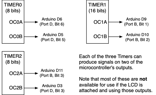
When working with the Timer/Counter modules the output signals are always referred to by the names shown above inside the boxes such as "OC0A" or "OC2B". It's important to be aware that that these signals share the connections to the microcontroller with the digital I/O lines we have been working with as shown above. For example OC2A is the same connection on the Arduino as the Port B, bit 3. At any one time, only one module, either the Timer/Counter or the digital I/O can be using the line. For example, if the Timer 1 is outputting a signal on the OC1A pin, then Port B, Bit 1 can not be used as a digital I/O by putting bits in the PORTB register.
One common use of the Timer/Counter modules in the Atmel microcontroller used on the Arduino Uno is to generate Pulse Width Modulation (PWM) signals. Please watch the video and review the slides that are linked on the Assignments page to learn more about pulse width modulation.
To generate PWM signals the timer has to perform two tasks. First it has to generate pulses with a constant period. The period of the pulses is the time from the 0→1 transition of one pulse until the next 0→1 transition. To generate pulses at a fixed period the timer has to count the clock signal until the pulse period has been reached and then reset back to zero and start over.
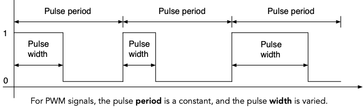
The second task for the timer is to control the width of the pulse which is the amount of time during the pulse period that the output is in the high or logic 1 state. The pulse output goes to the one state at the beginning of the pulse period, then at some point during the pulse period the timer must terminate the pulse by setting the pulse output to zero for the rest of the pulse period.
When working with PWM signals, your program configures the timer to generate the signals with the desired pulse period at the start of the program and never changes this setting since the pulse period is fixed value. As the program operates, it modifies or "modulates" the pulse width as needed to generate the proper signal.
PWM Control of an LED
Early in the semester you experimented with changing the brightness of an LED by altering the value of the current limiting resister so as to change the amount of current flowing through it. In that experiment the LED was glowing at all times but at different levels of brightness. In this task you will use a PWM signal to control the brightness of an LED by rapidly turning it on and off. When the LED is on, it is on at full brightness, but by varying the PWM pulse width we can controls how long it is on, and this changes the brightness of the LED as perceived by the human eye.
For this task we will be using Timer/Counter2, one of the 8-bit Timer/Counters. In the PWM mode we will be using, each period of the pulse is limited to the length of time it takes the timer to count from 0 to its maximum value of 255. The timer simply counts up to the maximum count value and then starts over. The relationship between count value, prescalar and time is given by

We will use the prescaler to divide the 16Mhz clock by 1024, so the period of our pulses will be

or

For this task we will be using Timer2 in what is called "Fast PWM" mode and this is illustrated below. At the start of the pulse period (count = 0) the OC2A output signal, which appears on Arduino port D11 (Port B, pin 3), will go to the high state to start the pulse. Register "OCR2A" is used to store a value that determines the pulse width by telling the timer when to terminate the pulse. During each pulse period, the timer counts up incrementing the count value, and when it reaches the value in OCR2A the output signal goes back to zero while the timer continues to count up to 255. The counter then resets back to zero and the process is repeated for the next pulse.
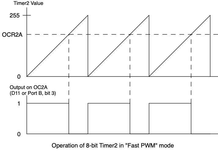
Your program will be have the job of changing the value in OCR2A in order to change the width of the pulse.
Task 1: Circuit for controlling an LED
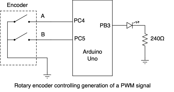
The circuit for this lab is shown below. The rotary encoder is connected to the PC4 and PC5 inputs. Note that this is different from the inputs used in Lab 7 so make sure to rewire it correctly. The LED and current limiting resistor is connected to output PB3.
Task 2: Generate the PWM signal
For this lab you should be able to start with a copy of the lab 7 program that uses interrupts to handle the inputs from the rotary encoder. Do the following tasks.
- Make a lab8 folder and copy your lab7.c to it and rename it lab8.c. Also copy the lcd.c and lcd.h files, and copy the Makefile and modify it as needed.
- We won't be using Timer/Counter1 (TIMER1) in this part of the assignment, so comment out any call to
timer1_init. You can leave the code for this function in the program since we will be using TIMER1 later in the assignment. - Add the following function to your program (or modify one already there) to initialize Timer/Counter2 to operate as described above for PWM generation. Make sure to have a call to this function somewhere at the start of your program.
void timer2_init(void) { TCCR2A |= (0b11 << WGM20); // Fast PWM mode, modulus = 256 TCCR2A |= (0b10 << COM2A0); // Turn D11 on at 0x00 and off at OCR2A OCR2A = 128; // Initial pulse duty cycle of 50% TCCR2B |= (0b111 << CS20); // Prescaler = 1024 for 16ms period } - Set the DDR bit for Port B, bit 3 to a one to make it the PWM pulse output.
- In this task we will not be using the Pin Change Interrupts so find the line in your code that enables these interrupts and comment it out. Don't delete the line sine we will be using later in this lab assignment. The line probably looks something like this.
PCICR |= (1 << PCIE1); - In Lab 7 the encoder was connected to PC1 and PC5, but in this lab we will be using PC4 and PC5. Changes will have to be made to the program in a few places because of this.
- Change the line that turns on the pull-up resistors so it is now enables the resistors on PC4 and PC5.
- Other changes will have to be made to the interrupt routines and that will be covered later.
For the checkpoint part of this lab we will be using the 'A' signal on input PC4 from from the rotary encoder as a switch to determine which of two PWM width signals to generate.
- If the A input is 0, the PWM signal should have a 20% duty cycle (high 20% of the period, low for the other 80%). The
OCR2Avalue should be set to 255 x 0.2 = 51. - If the A input is 1, the PWM signal should have an 80% duty cycle. The
OCR2Avalue should be set to 255 x 0.8 = 204.
The main loop for the program should consist of the following.
- Read the 'A' input bit.
- If A is zero, set
OCR2Ato 51, else set it to 204.
Once the program is downloaded, rotating the encoder slowly should make the LED change brightness between two levels as the 'A' input changes and this causes the PWM width to change.
If the LED brightness is changing, turn on an oscilloscope and hook the probe to the LED output and confirm that the PWM signal is changing between 20% and 80% as the encoder is rotated. Show this to a CP to record that you have the checkpoint task completed for this lab.
Checkpoint: Show that rotating the encoder causes the brightness of the LED to change, and show the PWM signal on a scope to a CP for the checkpoint credit.
Task 3: Using the rotary encoder to adjust the PWM signal
In this task we will use the rotary encoder to change the width of the PWM pulse width smoothly between 0% and 100% of the period rather than just having it change between 20% and 80%.
Much of the code for this task can be reused from Lab 7 that was using the rotary encoder with interrupts. For the PWM output some changes will have to be made to the code.
- First uncomment the line that enables the Pin Change Interrupts on Port C bits that you commented out in Task 2 above. From now on we will be using the Pin Change Interrupts to handle the rotary encoder inputs.
- Modify the line that sets up the mask value in the PCMSK1 register that determines which pins can generate Pin Change Interrupts to handle the encoder connected to PC4 and PC5.
- Change the lines that read the values in the PINC register to be testing PC4 and PC5. This is probably done in the main program when finding the initial state, and most importantly in the ISR for the encoder.
- Just like in Lab 7, your Pin Change Interrupt ISR should be where you check the encoder input bits and determine whether to increase or decrease the count value. Now add code to this ISR to limit the count value to stay between 0 and 255. This number has to fit in the eight bit OCR2A register.
- At the beginning of the program, initialize the variable that is modified by the encoder to the initial value that was put in the OCR2A register in the timer2_init function. This will prevent the value from jumping around the first time the encoder state is changed.
- As in Lab 7, your "
while (1)" loop in the main program should check to see if the ISR has set a flag that the count has changed. If it has changed, print the new count value on the LCD, but add code to also copy that new count value into the OCR2A register. That way as you rotate the encoder and change the count value, the number on the LCD is updated and the PWM pulse width will change. - Try running the program and confirm that your rotary encoder can make the count value change between the limits of 0 and 255.
- To confirm that the pulses are being created as specified, use an oscilloscope to look at the pulses on the OC2A output (Arduino port D11). You should be able to see the pulse width change as you rotate the encoder. If you feel it's taking too many turns of the encoder to cover the full range, change your program to increment and decrement the count value by more than one each time the encoder changes state.
- You should be able to adjust the LED brightness from full on to very dim by turning the encoder knob. Note that at the minimum PWM width (OCR2A = 0), the PWM signal will be high for one count of the timer, and this will be enough for the LED to still glow a little bit, so don't expect it to be completely off.
PWM Control of a Servo Motor
The next thing we want to do is use the PWM signal to control a servo motor. Servo are designed to operate using a PWM signal with 20ms period, and the pulse width should only vary between 0.75ms to 2.25ms. In the task above where we controlled the LED, we used a pulse period of 16.4ms since that was the longest we could get from the 8-bit Timer/Counter2. In order to get the recommended 20ms pulse period, for this part of the lab we will use the 16-bit Timer/Counter1 to control the servo motor.
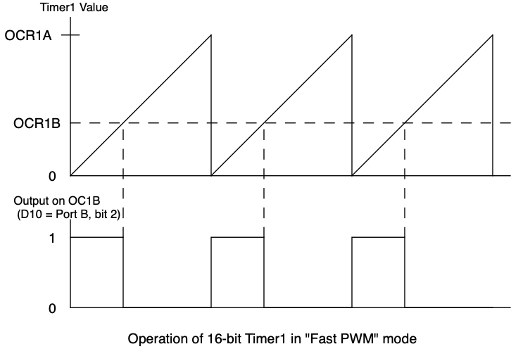
Timer/Counter1 has two internal 16-bit registers that are used to generate the PWM pulses. In the timer mode we will be using, register "OCR1A" is used to determine the pulse period by storing the value the timer should count to before resetting and repeating. Register "OCR1B" is used to store the value that determines the pulse width by telling the timer when to terminate the pulse. The pulse is produced on the OC1B output, which is Arduino port D10 (Port B, pin 2). The OC1B output will go high at the start of the pulse period (counter = 0) and when the timer reaches the value in OCR1B it will set the pulse output back to zero. The timer then continues to count until it reaches the value in OCR1A. At that point it resets to zero and starts the process over. This is illustrated the figure below. Needless to say, the value in OCR1B should be less than the value in OCR1A.
Before starting to write the code for this task, first figure out what values will be placed in the OCR1A and OCR1B registers to generate the PWM signal as specified above. Using the same process you used in the stopwatch lab, find a combination of a timer prescaler of either 1, 8, 64, 256 or 1024, and an OCR1A value that fits in 16-bits (<65,536), that gives a pulse period of 20msec. The count value to go in OCR1A can be calculated from
For example, with time=0.02 (20msec), find the count for a prescaler of 1. Then repeat the calculation for a prescaler 8, then for 64, etc., and determine which prescalers yield count values that are less than 65,536. There may be more than one combination of count and prescaler that work.
With the prescaler and OCR1A count selected you know the rate that the timer is counting at. Now use that same prescalar value in the above equation again to find the count values that will go in OCR1B to give delays of 0.75msec and for 2.25msec. These are the counts for the minimum and maximum pulse widths you will be using, and the encoder will be used to change the OCR1B value between these limits. Turning the encoder one way will cause the program to increase the value in OCR1B making the pulse wider, turning it the other will decrease the value to make the pulse narrower.
Task 4: Controlling a servo motor
In this task you will add code to your program that controls the LED so the encoder is controlling both the LED and the servo motor at the same time. As the encoder is rotated, the LED gets brighter or dimmer, and at the same time the servo motor rotates in one direction or the other.
Timer/Counter1 uses the OC1B output signal which is also used by the LCD. For the remainder of this lab remove the LCD from the Arduino. With the LCD removed you will have to reconnect the wires to the encoder and LED (PC4, PC5, and PB3) and ground to go directly to the Arduino. Once you have done that, confirm that the brightness of the LED can still be controlled by the encoder the same as it was when the LCD was attached.
Before modifying your program to control the servo motor, make a copy of your lab8.c just in case you have to go back to it for some reason. For the second part of the lab, the following tasks will need to be done.
- Remove all the calls to LCD functions in the program since the LCD is not installed on the Arduino.
- Create a new function
timer1_init()that will initialize Timer/Counter1. This function should contain code to perform the steps listed below. Refer to the ATmega328P datasheet or the class notes that discussed the operation of Timer/Counter1 to determine which register the various bits are located in.- Set the Waveform Generation Mode bits (WGM13 - WGM10) to 1111. Two of these bits are in register TCCR1B and the other two in TCCR1A.
- In register TCCR1A, set the COM1B1 bit to a one. This will make the OC1B output line (Arduino port D10, or Port B, bit 2) serve as the pulse output.
- Set the OCR1A register to the value determined above. For an initial condition for register OCR1B, use a value halfway between the two limits which should result in a pulse width of 1.5msec.
- In register TCCR1B, set the Clock Source bits (CS12, CS11, CS10) to the correct values for the prescaler you selected above. Check the manual or the class notes to find these values.
Important: Make sure to call this function at the start of your program just like you call the timer2_init function.
- The PWM signal will be produced on the OC1B output pin, so set the DDR bit for Port B, bit 2 (Arduino port D10) to a one to make it an output.
When the program is running, rotating the encoder will change the PWM signal from Timer2 that control the LED, and also change the PWM signal from Timer1 that rotate the servo motor. Add code in the ISR or the main program to accomplish this.
- Define a new global variable to hold the PWM width value for Timer/Counter1. This is the variable that your ISR will change as the encoder is rotated, and then is loaded into OCR1B to vary the pulse width.
- In the Pin Change Interrupt ISR, add code so that whenever there is a state change, the variable you just created is incremented or decremented. Note that your ISR is now incrementing or decrementing two variables for each state change, one for each timer.
- Add code to the ISR to keep the Timer/Counter1 PWM width value between the limits you calculated above. It should not go below the minimum pulse width value, and should not go above the maximum pulse width value.
- Modify the main program so that whenever there has been a encoder state change, the new value for the Timer1 PWM width is copied into the the OCR1B register in the same way you update the Timer2 value for the LED.
To confirm that the pulses are being created as specified, use an oscilloscope to look at the pulses on the OC1B output (Port B, bit 2 or Arduino port D10). You should be able to see the pulse width change as you rotate the encoder. Check to make sure that
- The pulse period is 20ms.
- The minimum pulse width is 0.75ms
- The maximum pulse width is 2.25ms
- The pulse width changes smoothly and doesn't jump around as the encoder is turned.
You must demonstrate your working PWM signals by showing them on an oscilloscope to an instructor. Do not connect the PWM signal to the servo motor until an instructor has confirmed that the signal is correct.
Connecting the Servo Motor
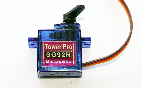
To complete this lab, get a servo motor from the instructors if you don't already have one in your lab kit. Each servo comes with a set of black plastic arms that can be placed on the servo motor's shaft. Pick one of them and press it down onto the motor's shaft. This will make it much easier to see the rotation of the motor.
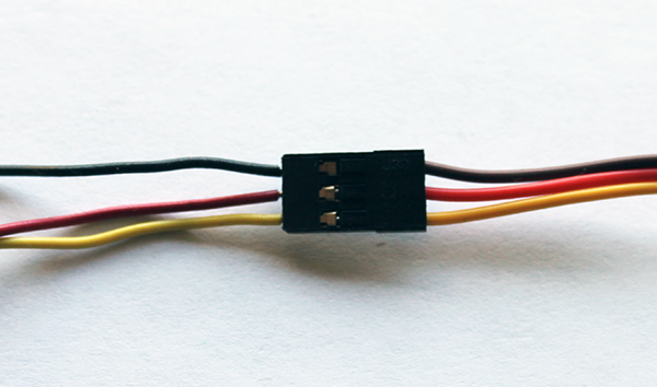
When connecting the motor to your Arduino, first disconnect the power to your Arduino before connecting the motor. The cable to the motor has a three conductor connector with three wires going into it, red for power, black for ground and yellow for the PWM signal. Using a piece of breadboard hookup wire, make a connection from the +5V on the Arduino to the red wire by inserting the end of the wire into the connector socket for the red wire as shown in below. Do the same to connect the Arduino ground to the black wire, and from the Port B, bit 2 (D10) output pin to the yellow wire.
Once you reconnect the power to your Arduino the motor should move to the initial position as set by your PWM signal.
Try rotating the encoder knob and see if the motor responds correctly. Check to see that you can move the motor through an arc of about 150 degrees. The LED brightness should also change as the position of the motor changes.
Results
When your program is running you should be able to confirm the following
- PWM signal period is correct on scope
- PWM minimum and maximum width is correct on scope
- LED brightness changes smoothly from bright to almost off
- Motor turns smoothly in both directions
Once you have the assignment working demonstrate it to one of the instructors. The answers to the review questions below should be edited into the Lab8_Answers.txt file. The Lab8_Answers.txt file and all source code (lab8.c, lcd.c, lcd.h, and Makefile) must be uploaded to the Vocareum web site by the due date. See the Assignments page of the class web site for a link for uploading.
Please make sure to save all the parts used in this lab, including the servo motor, in your project box. These will be needed for labs throughout the rest of the semester. We suggest also saving all the pieces of wire you cut and stripped since those will be useful in later labs.
Review Questions
Answer the following questions and submit them in a separate text file ("Lab8_Answers.txt") along with your source code.
- Billy Bruin wants to control a servo motor like the one used in Lab 9 but only has the 8-bit Timer/Counter0 available to use to generate the PWM signal. He says this won't work since the maximum pulse period you can get from the 8-bit timer is 16.4ms and servo motors need PWM signals with a 20ms period. Tammy Trojan decides to try using the 8-bit timer anyway just to see if it will work. Assuming she sets it up for the maximum period of 16.4ms, what values will she have to put in the OCR0A register to generate the minimum pulse width of 0.75ms, and the maximum pulse width of 2.25ms?
- When Timer/Counter1 is counting, the count value is kept in the TCNT1 register and is constantly being compared for equality (and only equality) to the values in the OCR1B and OCR1A registers to determine when to terminate the PWM pulse or to end one pulse period and start the next. Suppose at some point your program adjusts the PWM width by changing the OCR1B register, and the new OCR1B value is lower than the value that is currently in the TCNT1 register. What will happen to the output signal during this pulse period?