EE109 – Spring 2023: Introduction to Embedded Systems
Lab 5
Analog to Digital Conversion
Honor Statement
This is an individual assignment. The code you write, use for the demo and submit should be wholly your own and not produced by working in teams or using, in part or in whole, code written by someone else (found online, from a fellow student, acquaintance, etc.). You will be asked to verify this when you submit your code on Vocareum by signing your name in the honor.txt file on Vocareum. Penalties for violation include a 0 on the assignment and a potential further deduction or referral to Student Judicial Affairs.
Introduction
This lab exercise is an extension of Lab 4 where you developed some of the software to interface your Arduino with an LCD display. In this lab you will learn how to use C functions to display short text strings on the LCD. Once that is done you will use the Arduino's analog-to-digital (ADC) conversion capability to interface the microcontroller to a variable resistor, also known as a "potentiometer", and also to the buttons on the LCD module. The goal for this lab is to implement a simple 3 number combination lock on the LCD using the potentiometer and buttons. Writing the program will involve learning how to configure the ADC module by setting various register bits, how to initiate a conversion and how to draw characters on the LCD screen based on the conversion results.
Recommended viewing: Video on analog-to-digital conversion
Recommended reading: Chapter 7 in "Make: AVR Programming" on Analog-to-Digital Conversion
For a copy of the Lab 5 grading sheet click here.
Getting Started
Set up your Lab 5 assignment the same way we have done previous in labs by making a lab5 folder in your ee109 folder. You can copy the Makefile, lcd.c and lcd.h from Lab 4 to the lab5 folder.
From the class website download the file "lab5.zip" and extract the contents into the lab5 folder. The Zip file contains four files:
lab5.c- a template for the main part of the Lab 5 programadc.c- a template for the ADC routinesadc.h- header file for the ADC routinesLab5_Answers.txt- Edit this file to answer the review questions at the end of this web page, and upload to Vocareum.
In previous labs we put the routines for the LCD in a separate file, lcd.c, with the function definition in lcd.h. For using the ADC, we now want to do the same thing by having the ADC functions and definitions in the files adc.c and adc.h.
Make sure to update your Makefile to replace lab4.o with lab5.o, and also add adc.o to the OBJECTS line.
Displaying characters
The LCD display uses the ASCII character codes to determine which characters to display. Any byte written into the LCD's data register will result in the character with that ASCII code being displayed on the LCD and the cursor that indicates where the next character will go is advanced one position to the right. For example if the bytes with values 0x55, 0x53, 0x43 are written to the data register one after the other, the characters "USC" will appear on the screen.
In order to write characters to various places on the display, we need to ability to move the cursor to one of the 32 character positions prior to sending the ASCII data. Each character position on the display has a unique address in the same way that bytes in computer's memory have unique addresses. The "lcd.c" file contains the function lcd_moveto that accepts as arguments a row (0 or 1) and column number (0 to 15) and translates that to the command to move the cursor to the position with the correct address. For example, to move the the fifth column (column 4) on the second row (row 1), we would use this command.
lcd_moveto(1, 4);
The lcd_moveto function is designed to hide from the user the ugly details about how the LCD actually addresses the characters in the display but instead just uses a row number (0 or 1) and a column number (0 to 15).
Once the cursor has been moved to a position, any subsequent data bytes sent will cause characters to appear starting at this position and extending to the right. Note: if you write more characters than will fit on a line, it doesn't automatically wrap to the next line. If you want the additional character to go on the second line, you have to use lcd_moveto to position the cursor there before writing the additional characters.
Character strings in C
The lcd.c file contains a function, lcd_stringout, that will write to the LCD a string of multiple ASCII characters starting at wherever the LCD cursor is located. In the C language these are often called "C strings" and are simply a "char" array containing the characters to be displayed.
It is very important that this array be a proper and correct collecction of characters or garbage is likely to end up being displayed on the LCD. A array that holds a string of characters in C has to
- Contain any number of printable ASCII character codes. The code for the first character in the string is in array location 0, the next in location 1, etc.
- Contain a zero byte (also called a "NULL" byte) in the next array location after the last ASCII character to be display. This is just a byte is containing the value zero.
There are many ways to create a C string. For example to make a string containing "USC" we could do this.
char school[4] = "USC";
The compiler puts the ASCII code for 'U' (0x55) in school[0], the code for 'S' (0x53) in school[1], the code for 'C' (0x43) in school[2] and puts a zero byte in school[3]. It's very important that the array was declared as size 4 even though we only had 3 characters to put in it since the compiler needs the extra place in the array for the zero byte.
We could have also assigned the array values individually.
char school[4];

school[0] = 'U';
school[1] = 'S';
school[2] = 'C';
school[3] = 0;
The last line could also have been written as
school[3] = '\0';
but it would NOT be correct to write the last line as
school[3] = '0';
since this assigns school[3] to be the ASCII value of 0 (0x30).
No matter how the C string is created, it is very important that it is a correctly formatted array with the zero byte at the end. If the array elements do not contain proper ASCII codes, or the zero byte is missing, all sorts of strange things will appear on the LCD when it is sent to the LCD, and the Arduino's program will probably die at that point.
Displaying strings of characters
To write a string of characters to the LCD, the "lcd.c" file contains the the function lcd_stringout. This routine writes a string of multiple characters, as described above, to the LCD starting at the current cursor position. The argument to lcd_stringout must be pointer to a standard C string, an array of "char" variables each containing an ASCII character code, terminated by a zero byte. Normally in programs we just write the name of the array containing the C string as the function argument and the compiler knows to pass a pointer to that string when the function is called.
Open up the "lcd.c" file and look at how the lcd_stringout function works. It contains a loop that does the following:
- Looks at a value in the string (a character)
- If character is the NULL character (i.e. the value of the character variable is zero) that is at the end of all C strings, all the characters in the string have been sent to the LCD so the loop is done and the function returns.
- Otherwise, use the lcd_writedata function to send the character to the LCD.
- Move to the next element in the string.
Keep in mind that the lcd_stringout function has no idea where it is writing characters on the screen. It just writes characters at whatever place on the screen that you moved the cursor to with the lcd_moveto function. It doesn't complicate things by trying to wrap text onto another line if it goes past the right side of the LCD. It just writes all the characters in the string, one after another, even if some go past the right side and can't be seen.
Displaying binary data
The lcd_stringout function will display a C string of characters on the LCD, but what about displaying the value of variable that contains some binary value? Many people try doing the following only to find out that it doesn't work.
int x = 1234;

lcd_stringout(x);
The "x" variable contains the value 1234. It's not the name of an array containing the ASCII codes for '1','2', '3', '4' and then a zero byte. If we try the above code the LCD will end up with either nothing or garbage displayed on it, and the Arduino's program may stop running.
It's important to remember that the LCD only displays ASCII characters. Any other type of value must somehow be converted into an array of ASCII characters, a C string, before it can be displayed. In the section below we will discuss the snprintf function which is used to convert binary variables to strings of ASCII codes.
Creating character strings
Since the LCD is used to display strings of characters, it's necessary to have a efficient way to create the strings to be displayed. Constant strings are no problem and can be given as an argument to the lcd_stringout function.
lcd_stringout("Hello, world");
It gets more complicated when you need to create a string containing variable values, such as numbers. For example, in C++ when you write
cout << "Answer is " << x << endl;
cout is converting the numeric value of x into the ASCII representation of that number.
In C, the best tool for creating character strings is the snprintf function that is a standard part of most C languages. Important: In order use snprintf, or any other routine from the C standard I/O library, you must have the following line at the top of the program with the other #include statements.
#include <stdio.h>
The snprintf function is called in the following manner
snprintf(buffer, size, format, arg1, arg2, arg3, ...);
A quick example is:
char buf[17];
int x = /* some value */
snprintf(buf, 17, "Answer is %d", x);
lcd_stringout(buf);
The arguments for snprintf are:
- buffer
The destination char array large enough to hold the resulting string including the NULL byte that has to be at the end. For example, if you want to store the string "Hello" in a array, the array must be at least 6 elements long.
size
The size of the destination char array. This tells the snprintf program the maximum number of character it can put in buffer regardless of how many you try to make it do. Keep in mind that the snprintf functions always puts a NULL byte at the end of the string it creates. If you ask it to put "12345" in an array of length five, you will end up with the string "1234".
format
The heart of the snprintf function is a character string containing formatting codes that tell the function exactly how you want the following arguments to be formatted in the output string. More on this below.
arguments
After the format argument comes zero or more variables containing the values to be placed in the string according to the formatting codes that appear in the format argument. For every formatting code that appears in the format argument, there must be a corresponding argument containing the value to be formatted.
The format argument tells snprintf how to format the output string and has a vast number of different formatting codes that can be used. The codes all start with a percent sign and for now we will only be working with two of them (and a simple variation of one of them):
- %d
- Used to format decimal integer numbers. When this appears in the format string, the corresponding argument will be formatted as an decimal integer number and placed in the output string. It will only place as many characters in the buffer as needed to display the number. A number from 10 to 99 will take up two places, a number from 100 to 999 will take up three places, etc. A useful variation of this is to specify a minimum field width by using the form "%nd" where the 'n' is the minimum number of spaces the converted number should occupy. If it takes less space than 'n' characters it will be right justified in the 'n' character field with spaces to the left. For example, a format of "%4d" will print an argument of 65 as " 65" with the number right justified and two leading spaces.
- %s
- Used to format string variables. When this appears in the format string, the corresponding argument will be assumed to be a string variable and the whole string variable will be copied into the output string.
The format string must have the same number of formatting codes as there are arguments that follow the format argument in the function call. Each formatting code tells how to format its corresponding argument. The first code tells how to format "arg1", the second code is for "arg2", etc. Anything in the format argument that is not a formatting code will be copied verbatim from the format string to the output string.
Example: Assume you have three unsigned char variables containing the month, day and year values, and a string variable containing the day of the week, and you want to create a string of the form "Date is month/day/year = dayofweek".
char date[30];
unsigned char month, day, year;
char *dayofweek = "Wednesday";
month = 2
day = 14;
year = 18;

snprintf(date, 30, "Date is %d/%d/%d = %s", month, day, year, dayofweek);
After the function has executed, the array "date" will contain
Date is 2/14/18 = Wednesday
Since you told snprintf that the size of the array was 30, the maximum number of characters it will put in the array is 29 since as with all C strings, the string has to be terminated with a null byte (0x00).
An additional example is shown here:
char x = 10, char y = 12;
char z = x - y;
char buf[12]; // make sure you add one spot for the null character
snprintf(buf, 12, "%d-%d=%d", x, y, z); // yields "10-12=-2" but not on the LCD
lcd_stringout(buf); // prints "10-12=-2" on the LCD
Beautifying Your Output
Often times we may want a number to take up a fixed number of spaces on the screen. For example if we print out 9 and then 10 the fact that 10 grew into a 2nd digit may make the visual layout look sloppy. We might want all our numbers to use 2 digits (if we know in advance that they will be in the range 00-99) or 3 digits (if we know the range will be 0-255). To do this we can add modifiers to the %d format string modifier.
- %2d will print the decimal number using 2 spaces leaving the first space blank for single-digit values 0-9.
- %3d will print the decimal number using 3 spaces leaving the first one or two blank.
We can also set the string to use 0-padding fill in blank spaces with 0s.
- %03d will print the decimal number using 3 spaces if needed and fill in unused digits with 0s. For example, 5 would be printed as 005, while 34 would be printed as 034.
A good reference for format strings can be found here.
Task 1: Write some strings to the screen - Checkpoint
We now have all the tools necessary to write something to the LCD screen. In this task, we want you to practice creating strings that contain variable values using snprintf(). To do this, you should:
- Near the top of
lab5.cadd the call tolcd_initto initialize the LCD display. - Add code to write two lines of text to the screen, before the while(1) loop which should have no code it at this time. The first line on the LCD should display your name (as much as will fit) to the first row. The second row should contain a string with your birthday that was created using snprintf, similar to the way the string above was formatted with today's date using numerical values and the "%d" format strings. It should be displayed somewhat centered on the bottom row and not just start at the 0-th column of the row. This ensures you understand how to use the
lcd_movetofunction. After both rows are displayed on the LCD, make the program delay for 1 second./* Call lcd_stringout to print out your name */ /* Use snprintf to create a string with your birthdate */ /* Use lcd_moveto to start at an appropriate column in the bottom row to appear centered */ /* Use lcd_stringout to print the birthdate string */ /* Delay 1 second */ while(1) { }
Compile and run (make flash) this basic skeleton code with the commands to show your name and birthdate.
Checkpoint: Show the lab staff your screen for checkpoint credit.
Using portable data types
Up to now we have been declaring variables as being char, short, int, etc. This is the traditional way of declaring variables in C, but more recent versions the C language standard also support data types that have the advantage of showing exactly how many bits are in the variable. This eliminates the problem of code being moved from one system to another and having the size of variables change.
| Traditional declaration | Portable declaration | Number of bits |
char
| int8_t
| 8 |
unsigned char
| uint8_t
| 8 |
short
| int16_t
| 16 |
unsigned short
| uint16_t
| 16 |
int
| int16_t
| 16 |
unsigned int
| uint16_t
| 16 |
long
| int32_t
| 32 |
unsigned long
| uint32_t
| 32 |
We are now using these portable type definition in several place in the Lab 5 code, and will continue to do so in subsequent lab.
Note: Due to the way the avr-gcc compiler works, the portable type definition can not be used in some cases. Functions like snprintf that expect an array of type char as the first argument will issue a warning if the equivalent portable definition (int8_t) is used instead. For functions that expect an array of type char, perhaps for a string of ASCII characters, continue to use the traditional declaration.
Task 2: Write the ADC routines
Information on using the ADC module is available in a lecture slide set. A more in-depth review of this material is provided in a separate document "Using the Atmel ATmega328P Analog to Digital Conversion Module" available on the class web site. Refer to any of these resources for information on configuring the various registers in the module and how to do the conversions.
The adc.c files contains the template for two routines that you will have to write.
- adc_init() - This routine initializes the ADC module. It only needs to be called once at the start of the program but must be called before making any calls to the routine that takes the samples.
- adc_sample() - This routine has one argument, the channel number (0 to 5) to use for the ADC sample. It starts an analog-to-digital conversion on the specified channel, waits for it to complete and then returns the 8-bit value to the calling program.
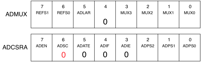
The adc_init routine must set up the proper values in the ADMUX and ADCSRA registers. Diagrams of the registers are provided on the Lab 5 grading rubric for you to fill in the values.
Important: When writing code to set or clear the bits in these registers by using the "<<" shift operations, you can use the name of the bit as shown in the diagram. For example, to set the ADEN bit to a one, the following can be done.
ADCSRA |= (1 << ADEN)
We strongly encourage you to use the symbolic bit names rather than the 0-7 bit number when doing set/clear/test bit operations.
Add code to adc_init to do the following:
- Set/clear the REFS[1:0] bits in ADMUX to select the high voltage reference. Using the AVCC reference is appropriate for this lab.
- Set or clear the ADLAR bit in ADMUX such that we will use 8-bit conversion results (not 10-bit).
- Set/clear the ADPS[2:0] bits in ADCSRA to select an appropriate prescalar value.
- Set the ADEN bit in ADCSRA to enable the ADC module.
- The other bits should be left as zeros. The ADSC bit (shown below in red) will be set to a one later in your code, but in the initialization of the registers is should be a zero.
The adc_sample routine is called to acquire a sample of the analog signal from the ADC. The channel to sample is specified as an argument from 0 to 5 when calling the adc_sample routine. The adc_sample routine is declared as a "unsigned char" function and the return value contains the result of the conversion and can be saved in an unsigned char variable. For example, to acquire a sample from ADC channel 2 and put the value in the variable data, the code would be
data = adc_sample(2);
The routine should do the following.
- Set/clear the MUX[3:0] bits in ADMUX to select the input channel as specified by the argument to the function. Hint: Use bit copying.
- Set the ADSC bit in the ADCSRA register to a 1. This starts the conversion process.
- Enter a loop that tests the ADSC bit each time through the loop and exits the loop when ADSC is 0. This indicates that the conversion is now complete.
- Copy the 8-bit conversion result from the ADCH register and return it to the calling program.
The LCD Buttons
The buttons on the LCD use the ADC to determine which, if any, are being pressed. This is different than how buttons in previous labs were interfaced to the Arduino. Rather than having all the LCD buttons produce an individual digital signal, all five of them are instead interfaced through a multistage voltage divider creating a single analog signal that can be measured by the ADC. Depending on which button was pressed, or none, this circuit produces a different voltage between 0 and 5 volts, and this signal is attached to the ADC Channel 0 input to the Arduino. By using the ADC to convert this voltage to a number it's easy to determine if one of the five buttons was pressed.
Task 3: Determine the LCD buttons value
When a button is pressed the analog voltage on ADC channel 0 changes to a unique value that identifies the button that was pressed. However in order for your program to determine which button was pressed you have to know what the ADC output is for each button. The easiest way to do that is to write code to loop continuously reading the ADC result and writing the value to the LCD.
Use the ADC routines you just wrote to give the program the ability to use the ADC to read the button's analog signal. In the while(1) loop of the main routine add code to do the following.
- Call
adc_samplewith an argument of zero to read the value of the ADC channel 0 and store the returned value in a variable. - Use the snprintf routine to format the ADC result into a string of numerical characters that can be displayed. (e.g. something like snprintf(buf, 5, "%4d", adc_result);
- Use your lcd_moveto function to move the cursor to the first character position on the first row.
- Use your lcd_stringout function to print the string on the display
Once the program is running, try pressing each button and see what value is displayed. You can record the values shown for each of the buttons on the Lab 5 grading sheet. These values will be used in later tasks. You should note that the ADC conversion results may not always be exactly the same each time a button is pressed. Due to electrical noise and thermal effects it may return, for example, 124 one time, 125 another and 126 yet another time. Your code must take this into account when working with the ADC results.
The Variable Resistor
For this lab assignment one of the inputs to the ADC of the Arduino will come from a variable resistor or potentiometer (or "pot" for short) hooked up to be a voltage divider. A potentiometer as shown below is a three-terminal device that has a fixed resistance between two of its wires and a third wire, sometimes called the "slider" that can be adjusted to give anywhere from zero to the full resistance between the slider wire and the other two. In short, the potentiometer operates as a voltage divider (two resistors in series) where the resistance in the numerator can be adjusted by dialing/spinning the "pot". Turn it fully one direction and you will see 0V on pin 2. Turn it fully in the other direction and you will see VS (5V) on pin 2. At any position in between you should the voltage on pin 2 scale linearly.

In schematic diagram above of a potentiometer, the total resistance between the top and bottom terminals of the potentiometer is given by R. Internally R can be viewed as two resistors R1 and R-R1 and in series so the resistance between the top and bottom terminals is fixed at R. Changing the position of the potentiometer's control changes the resistance of R1. Since the value of R is fixed, as R1 increases, R-R1 must decrease by an equal amount, and similarly if R1 goes down R-R1 must go up.
When hooked up as a voltage divider as above, we can see that V is given by

As the position of the slider is adjusted the value of R1 can change from R (making V=VS) to zero (making V=0). By adjusting the slider we can get any voltage from 0 to V=VS to appear on the slider terminal that will be connected to the ADC input.
Get the potentiometer from the parts provided in your kit and examine it. The resistance between the two fixed terminals (R in the above) is marked on the top next to the round control that is rotated. It should say "102" which is the resistance in the same format as used for marking fixed resistors: 1, 0, and two more zeros = 1000Ω.
The Circuit
The circuit is shown below. Note +5V and ground to the potentiometer are connected to your Arduino board's 5V and GND connectors.
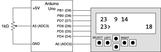
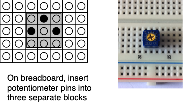
On the potentiometer, the two pins that are on a line parallel to the sides of the device correspond to the top and bottom pins as shown above. The slider pin is the one offset from the other two.
- Insert the potentiometer into your breadboard so that all three pins are in different 5-hole connection strips as shown below.
- Make a connection from the slider pin's 5-hole strip to the Arduino A3 (ADC channel 3) input.
- Connect one of the other two pins (either one) to the 5V source on your Arduino board.
- Connect the remaining pin to ground.
To confirm that you have it connected properly, use the multimeter to check that the voltage on the slider pin can be changed by rotating the control.
- Turn on the DMM and set it for measuring DC volts.
- Hook the black lead of the DMM to the Ardunio ground, and hook the red lead to the slider pin which is connected to A3.
- Plug in your Arduino's USB cable into your computer so there is power to the Ardunio and the Arduino is providing 5V power to the breadboard.
- Set the DMM to measure DC volts and try rotating the pot with your screwdriver. The indicated voltage should change between +5V and ground as you rotate the pot.
Task 4: Check potentiometer and ADC routines
Before trying to use the potentiometer in the next part of this lab we recommend you check to see if it and the ADC routines are working. Your lab5.c file should still have the code to read the ADC value on channel 0 for the buttons. Change the channel number in the adc_sample function call to use channel 3 where the potentiometer is connected. Flash the new code to your Arduino, and then try rotating the potentiometer back and forth. The program should be displaying the numerical values of its conversions of the voltage on channel 3, and these should be close to 0 at one end of the rotation and close to 255 at the other. If you are not seeing this, you will need to fix the problem before using the potentiometer and ADC code in the next task.
Task 5: Write the combination lock
The combination lock works in the following manner.
- When your program starts it writes three random numbers in the range 0 to 31 on the top row of the LCD. These are the numbers that make up the combination of the lock.
- The left and right buttons are used to move a cursor to a position below one of the three numbers.
- The potentiometer is used to change a number in the lower right corner of the LCD screen between 0 and 31.
- Once the potentiometer is showing the a number that matches the indicated combination number, pressing the "Select" button copies this number into one of the three positions selected by the left and right buttons.
- After all three position have been filled by numbers that match the three numbers on the top row, the LCD shows that the lock has been unlocked.
- Once the lock has been unlocked, the program can just loop continuously doing nothing. It does not have to go back and start a new combination.
The picture below is an example of what is shown on the LCD. The three numbers of the combination (8, 23 and 25) are shown on the top row. The number from the potentiometer (16) is in the lower right. The first number of the combination (8) has been entered in the first position, and the cursor is showing that the next time the "Select" is pressed the potentiometer number will go in the second position below the 23.
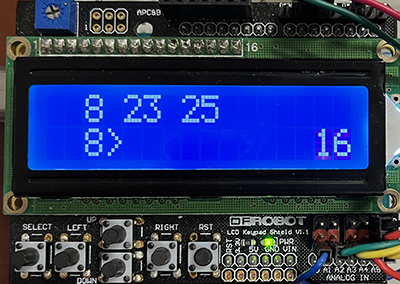
To see a short video demonstrating the operation of lock, click here.
At the start the program should do the following.
- Initialize both the LCD and the ADC
- Initialize the random number generation routines by calling the
rand_init()function. This function is provided for you in the lab5.c file. IMPORTANT: Therand_init()function uses the ADC so make sure you have called theadc_init()function before callingrand_init()or it will not work. - Display a splashscreen on the LCD showing the lab number (e.g. "EE109 Lab 5") on the top row and your name on the bottom row. The splashscreen should be visible for 1 to 2 seconds before the program clears the screen and proceeds with the rest of the program.
- Each time the program is run it should generate three different numbers for the combination. To do this, use the
rand()function to generate random numbers. Note: In order to use therand()function, the program must have the line "#include <stdlib.h>" near the top of the program.- Each time the
rand()function is called it returns a number between 0 and 32767 (0x7FFF). - Your program should then convert this to a number between 0 and 31 and display the number on the screen.
- Each time the
Once the above steps have been done the program should enter an infinite loop for the entering the combination numbers to unlock the lock. Each time through the loop the following should be done.
- Use adc_sample to see if either the left, right or select button has been pressed.
- If the left or right button was pressed change the position of the cursor indicating which of the three numbers will be entered:
- Erase the '>' at the old position by moving there and writing a space (' ') character.
- Move to the new position and write an '>' at that location.
- Delay at least 100ms to allow the user to get their finger off the button.
- Use adc_sample to acquire a new 8-bit value for the position of the potentiometer.
- The 8-bit value must be converted to a combination number between 0 and 31. To do this, think about the range of inputs and desired outputs. The ADC produces values 0-255 while we want 0-31. Furthermore, we want consecutive ADC values (as you slowly turn the pot) to produce the same output value. For example ADC value 0,1,2,...,n-1 should all produce output of 0 on the LCD screen, then n,n+1,n+2...,2n-1 should produce output of 1 on the LCD. Determine n and then think about a simple mathematical operation to convert the input ADC result to the desired output column.
- Write the number from the potentiometer in the second row of the LCD towards the right side of the line.
- If the "Select" button has been pressed, write the number from the potentiometer to the position of the second row selected by the left/right buttons.
- Check to see if all three numbers on the second row match the combination numbers on the first row. If so, print "Unlock" on the screen. The program can then enter an infinite loop to stop the program.
Results
When your program is running you should be able to
- Display your splash screen.
- Confirm that three different numbers are generated for the combination each time the program is started.
- Move the '>' left and right using the buttons on the LCD.
- Turn the potentiometer control back and forth with the screwdriver and see the number change smoothly from 0 to 31. It should not skip any values or spend significantly more time on one value than another.
- Press the select button to copy the potentiometer number to one of the three positions for the combination.
- When all three numbers on the second row match the ones on the first row, the "Unlock" message should appear.
Once you have the assignment working demonstrate it to one of the instructors. The answers to the review questions below should be edited into the Lab5_Answers.txt file. The Lab5_Answers.txt file and all source code (lab5.c, lcd.c, lcd.h, adc.c, adc.h and Makefile) must be uploaded to the Vocareum web site by the due date. See the Assignments page of the class web site for a link for uploading.
Please make sure to save all the parts used in this lab in your project box. These will be needed for labs throughout the rest of the semester. We suggest also saving all the pieces of wire you cut and stripped since those will be useful in later labs.
Review Questions
Answer the following questions and submit them in a separate text file ("Lab5_Answers.txt") along with your source code.
- To ensure a date appears in the format: MM/DD, what
snprintf()function could be used to ensure dates like 6/9 are generated in a character buffer as 06/09char buf[17]; int m = 6; d = 9; snprintf(buf, 17, /* you write the format string */, m, d);
- Review the conceptual operation of an ADC and use the given parameters to find the desired value.
- Your 8-bit ADC has Lo and Hi reference voltages of 1V and 4V, what digital number would result from sampling a 2.0V?
- Your 5-bit ADC has Lo and Hi reference voltages of 0V and 5V, what input voltage would yield a digital number of 12?
- Your 6-bit ADC has a Lo reference voltages of 2V. A voltage is sampled at 2.4V and the digital result is 26. What was the Hi reference voltage used by the ADC?