EE109 – Spring 2023: Introduction to Embedded Systems
Lab 1
Electronic Circuits
Introduction
This lab assignment has two purposes: to give you some experience assembling basic electronic circuits on the breadboard from your project box and using a couple of pieces of test equipment in the VHE 205 lab. Various circuits will be constructed and the test equipment will be used to make measurements to confirm some of the fundamental laws that apply to electronic circuits.
Each station in the VHE 205 lab consists of a collection of electronic test equipment. Some of the equipment is designed to generate signals, others are for observing signals. This equipment will be used in subsequent labs assignments so it is important that all students become familiar with the operation of the different items of test equipment.
A paper work sheet is provided in VHE 205 for recording answers to the questions below that will be turned in using the Lab1_Answers.txt file. To download a copy of the work sheet, click here.
Working With a Partner
The VHE 205 classroom has 18 workbenches with the electronic test equipment that will be used in this lab and the next. Since there are usually more than 18 students in the lab sessions, for these labs students may choose to work with a lab partner. Students can work either by themselves, or in groups of two or three, but not more than three.
If you can find an open bench and work by yourself we strongly encourage you to do so. Most of the future labs must be done individually so gaining as much experience as possible in wiring circuits and using test equipment will have benefits later.
When working with a partner, students should take turns operating the test equipment and doing the wiring. It's important that everyone get experience working with the lab equipment so don't assign one person to do all the electronic assembly work and measuring while the other just records results.
If working with a partner, both students still have to turn in their results on Vocareum by the due date. It is fine for students who have worked together to turn in identical Lab1_Answer.txt files when submitting results.
Create a Lab 1 Folder
In Lab 0 you learned how to create a new folder for a project, and now we want to do the same for Lab 1. In your "ee109" folder create a new folder called "lab1".
$ cd Desktop
$ cd ee109
$ mkdir lab1
The "ee109" folder should now contain a "lab0" folder and a "lab1" folder.
From the class web site, download the file lab1.zip. As was done in Lab 0, extract the contents and place them in the "lab1" folder. You should end up with one file in the "lab1" folder: Lab1_Answers.txt.
At several places in this assignment you will be asked to either calculate a voltage, current or resistance value, or to use test equipment to measures these. Your answers should be edited into the file Lab1_Answers.txt.
Important: The
Lab1_Answers.txtis a plain text file so it should be edited in a text editor like you use for editing your C source code. Don't edit it in a word processor. Also don't edit it on either Windows or Macs by simply double clicking on the Lab1_Answers.txt file since this may open up the file in the system's default editor and those can sometime mess up a plain text file.
If you don't want to edit the file while doing the lab, you can fill the answers in on the sheet provided in class and then transfer them to the file later.
Submission via Vocareum
We will submit all of our labs via a website called Vocareum. This site allows us to not only grade your code but to mark-up your code with suggestions and improvements to consider. All students will be added to the Vocareum service.
If you have already had a class that used Vocareum, you will not get a notification but instead can just login to vocareum.com and under your classes (or potentially the Home icon) you will now see EE 109 available. If this is the first time you've had a class at USC that uses vocareum.com you should receive an email invitation to sign up (create your account). Please do so! (Check your Clutter/Junk email if you don't see the invitation)
When you login to Vocareum you should be able to see a Lab 1. By selecting it you should be able to upload your Lab1_Answers.txt file. Be sure to hit Submit and not just save.
Your answers must be uploaded to Vocareum by the lab due date.
The Breadboards (Background)
Video Introduction - Protoboards
The solderless breadboard included in your project kit allow you to quickly build and modify a circuit by inserting the components and wires into the holes of the breadboard. Please get the breadboard from your project kit and take a look at it. In the center section of the board are around 60 sets of five holes on each side of the slot that runs down the center of the board. In the picture below the center of the board is running horizontally so the sets of five holes are actually above and below the center. Wires are inserted into these holes and inside the breadboard metal contacts at each hole will touch the wires and make an electrical connection. The metal contacts for each of the five holes in a group are connected together inside the breadboard as shown in the connection diagram on the right below. When you need to connect components and wires together, plug all of them into one set of the five holes and they will be electrically connected.
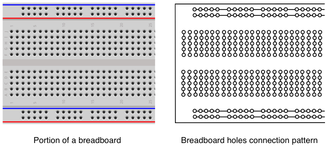
It's very important to understand that wires that are to be connected together must be plugged into holes in the same group of 5 holes. If you plug a wire into one group, and then another wire into a different group, they are not connected together electrically. If you need more than five things connected together, use wire to connect other sets of five holes to the first set to expand the number of connection points.
Along the sides of the breadboard (top and bottom in breadboard above) are columns of holes running in rows alongside blue and red lines. These are different in that all the holes in one column of holes are connected together. Thus we have four electrical nodes. Normally these are used for power and ground connections and are often referred to as "bus" connections. As a matter of convention, the holes next to the red lines should be used for power, and the ones next to the blue lines should be used for ground.
DC Power Supply (Background + Lab Tasks)
Video Introduction - Power and Digital Multimeters
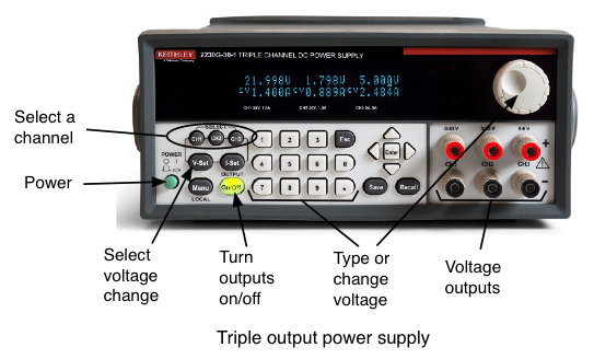
Electronic circuits require a power source in order to operate. Electrical power comes in two types: alternating current (AC) in which the voltages varies with time, and direct current (DC) where the voltage is a constant value. The power supplies in VHE 205 (shown below) are triple output variable-voltage DC power supplies meaning that they can simultaneously produce three different DC voltages and that the voltages can be changed by the user. Two of the outputs can produce voltages from zero to 30 Volts with current up to 1.5 Amps. The third output is variable from zero to 6 Volts with current up to 5 Amps. All of these limits are more than any of the requirements we will need in this class, so for all of the lab assignments you can use any of the three channels.
To set up the power supply for this experiment perform the following actions. We recommend you read this whole list of actions before you start performing them so you know what to expect
- Disconnect any cables from the red and black jacks on the front of the power supply.
- Press the power switch in the lower left corner to turn it on. The display should light up indicating the voltage settings for the three outputs. Below each voltage reading it should say "<OFF>". This indicates that while the output may be adjusted for a certain voltage, at this time the output is turned off. This is done to prevent circuits from being burned out in case the output voltage was set by the previous user to some voltage that is incorrect for what it's now connected to.
- Press the CH1 button and then the I-Set button so you can adjust the current limit on channel 1. The display should show the maximum amount of current the power supply will provide for the three outputs and the one for channel 1 should be blinking with an underline cursor under one of the digits. If no action is taken to adjust the current within about 4 seconds, the display stops blinking and you'll have to press the I-Set button again to make an adjustment.
- Rotate the wheel to the right of the display until the current limit for channel 1 is at least 0.3A. The exact value is not important, it just has to be something around there. If it's already set to some higher value, you can just leave it there.
- Press the CH1 button and then the V-Set button so you can adjust the voltage on output channel 1. The display should now show the voltages that are set for the three outputs and the one for channel 1 should be blinking with a underline cursor under one of the digits. If no action is taken to adjust the voltage within about 4 seconds, the display stops blinking and you'll have to press the V-Set button again to make an adjustment.
- The wheel to the right of the display is used to adjust the digits above the cursor. The cursor can be moved left or right with the triangular buttons next to the Enter button to make changes to each digit individually. Use the buttons to move the cursor until it is under the tenths of a volt digit, just right of the decimal point. Rotate the knob back and forth and note how the number above the cursor changes but the ones to the right (hundredth and thousandths of a volt) do not change. Also note that if you change the tenths of a volt far enough the number to the left of the decimal point will change accordingly as you move the voltage setting up or down. The voltage setting can be set by changing each digit individually, or by using the knob to change one of the fraction of volt numbers and doing a lot of spinning of the knob until the other digits also are set properly.
- Use the controls to set the voltage for channel 1 to 2.58 Volts. After you do this the display still shows "<OFF>" for each channel since the outputs have not yet been turned on.
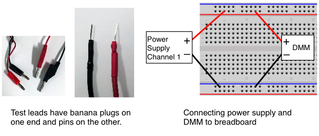
- From the rack of test leads in the right front corner of the classroom, get a red and black test lead. These should have a banana plug on one end and a metal pin on the other end (see below).
- Plug the red and black banana plugs into the Channel 1 output banana jacks (red to red, black to black.)
- Plug the pins on the other ends of the test leads into one of the the red and blue bus strips on the breadboard as shown below on the right.
Digital Multimeter (Background + Lab Tasks)
The digital multimeter (DMM) is a combination of several instruments and can be used to make a variety of measurements on electrical signals. At a minimum the DMM will have the following basic capabilities.
- Voltmeter for measuring AC and DC voltages. The voltage level is indicated in volts (V), millivolts (mV = 10-3V) or microvolts (μV = 10-6V).
- Ammeter for measuring AC and DC current. Current is measured in units of amperes or amps (A), milliamps (mA = 10-3A) or microamps (μA = 10-6A).
- Ohmmeter for measuring electrical resistance. Electrical resistance is measured in units of ohms (Ω), kilohms (kΩ = 103Ω), or megohms (mΩ = 106Ω).
Depending on how complex the DMM is it may also have other measuring features.
- Frequency meter. The frequency of a time varying signal is measured in cycles per second or Hertz (Hz)
- Capacitance meter. Measures the value of capacitors in microFarads (μF), nanoFarads (nF) or picoFarads (pF).
- Temperture measurements.
- Battery checking.
The Tektronix DMM4020 meters in VHE 205 are capable of making most of the measurements described above. To set up the DMM for this lab experiment, perform the following steps.
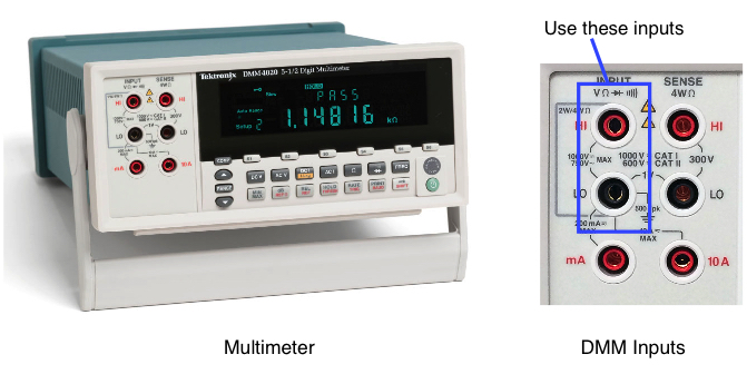
- Turn on the digital multimeter (shown below) by pressing the green button in the lower right corner.
- After it's done starting up, press the "DC V" button to set it for measuring DC voltages. All measurements except DC and AC current use the "HI" and "LO" input jacks at the far left side of the front panel under the word "INPUT". Don't use the two jacks under the word "SENSE" or the two bottom ones.
- From the rack of test leads get another set of red and black test leads with banana plugs and pins.
- Put the red and black banana plugs in the "HI" and "LO" jacks on the multimeter (red = HI, black = LO). Make sure you are using the inputs on the left under the word "INPUT".
- Plug the pins on the other ends of the test leads into the same red and blue bus strips
on the breadboard as was done with the leads from the power supply in the previous section. - Once both pairs of test leads from the power supply and DMM are attached to the breadboard, press the "On/Off" button just left of the digit "7" on the power supply keypad to turn on the power supply outputs. The button should illuminate with a green light and on the display the "<OFF>" indicators should be replaced by numbers showing how much current is flowing on each power supply channel (probably zero).
- The multimeter should now be showing the voltage it is measuring from the power supply. It probably isn't exactly 2.58 Volts but should be close.
- Question 1:
- What voltage was the power supply set for, and what voltage did the DMM measure?
Once you have recorded the voltage on the answer sheet, turn off the power supply outputs by pressing the illuminated green "On/Off" button. Note: Throughout this lab and ones in the weeks to come, when the instructions say to turn on or off the power supply outputs, do this with the green "<OFF>" button below the OUTPUT label. That button controls the power supply outputs but leaves the instrument itself turned on. Don't turn off the power to the whole power supply with the green POWER button or you will likely lose the settings you have made.
Resistor Color Code (Background + Lab Tasks)
Video Introduction - Resistors
In the bag of electronic parts in the project box you should find a some small resistors. The resistors have a cylindrical body with wire leads coming out of each end. The amount of resistance each has to the flow of electric current is indicated by the color bands around the body of the resistor. In this experiment, we will determine the resistance marked on each resistor and then use the DMM to measure the actual resistance of the resistor.
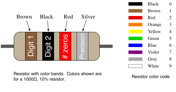
Resistance values are given in Ohms using a Greek omega character, Ω. For larger values of resistance it can be given in kilo-ohms (kΩ), or mega-ohms (MΩ). The body of the resistor is marked with a series of four color bands (see below) that are used to identify the resistance value. The parts bag should contain two resistors of each of three different resistances (6 total).
Select three resistors from the six provided that have three different sets of colors. To determine the resistor value from the color bands, first figure out which way to read the color bands. One of the bands at the end of the resistor body will be either a silver or gold color indicating the precision of the resistance value (silver = 10%, gold = 5%). The three bands at the other end indicate the value. Starting at the end away from the gold or silver band, the first and second bands are the first and second digits of the resistance value as given by the color codes shown below. The third band is the number of zeros that follow the first two digits. For example, a resistor with yellow, violet and red bands is a 4700 ohm resistor, which we write as 4700Ω or 4.7kΩ.
Make sure you have three resistors with different values (color bands are different) and then do the following:
- From the color bands determine the resistance of each of the three resistors. Note: You should have resistors of at least 100Ω and less than 1500Ω or 1.5kΩ.
Important: We will be using these resistors in later parts of this lab. The one with the lowest resistance will be referred to as resistor "R1", the middle resistance as "R2", and the one with the highest resistance as "R3". Record your results on the answer page.
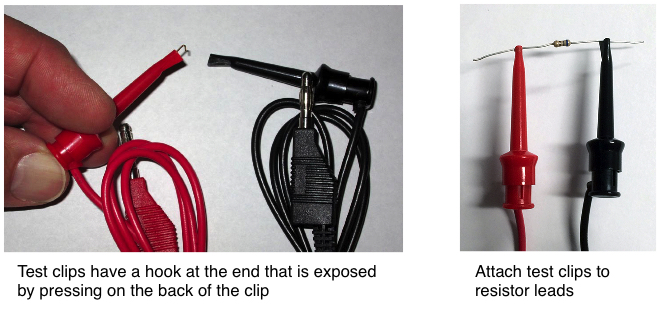
- Remove the test leads with the pins from the multimeter and replace them with the pair that have the test clips on one end and banana plugs on the other as shown below on the left. These test clips can be found on the rack in the back right corner of the classroom.
- On the front of the multimeter, set it for making resistance measurements by pressing the "Ω" button.
- In the upper right corner of the DMM display screen it should say "2X4Wire". If instead it says "4Wire", press the Ω button again to switch the DMM to 2x4Wire mode.
For each of the three resistors, do the following two steps and record your results on the answer sheet.
- Connect each of the two test clips to one of the two leads coming from the resistors as shown below on the right. Hold the body of the test clip with a couple of fingers and then with your thumb press the back of the test clip to cause the metal hook to extend from the other end of the clip. Resistors are "non-polarized" which means it doesn't make any difference which resistor lead is connected to the red or black test clip.
- Once both clips are connected to the resistor leads, the meter should display the resistance in either Ohms, KOhms, or MOhms. The values of the three resistors that you measured should be within about 5% of the component values you determined above by reading the color bands.
Important: Make sure you note what units of resistance are being shown on the meter. For example, if you are measuring a 470Ω resistor, the meter may display 0.470 KΩ. Remember that 0.47 kilohms is the same as 470 Ω.
- Question 2:
- What are the values of the resistors R1, R2 and R3 from the color bands?
- What are the values of the resistors R1, R2 and R3 by measuring with the DMM (round to the nearest integer)?
Schematic Diagrams (Background)
Electronic circuits are drawn using a schematic diagram. These show what types of components are in the circuit and their values, and also shows the interconnections between all the components. With a schematic of a circuit, an engineer has all the information needed to wire up the circuit in the way intended by the person who designed it. However it's important to remember that a schematic is not a diagram of how the components are physically arranged. The components can be laid out physically in numerous ways.
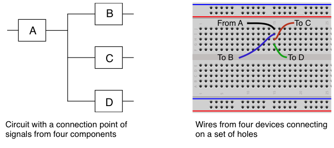
When assembling a circuit on a breadboard, examine the schematic and look for the connection points where multiple components must be tied together. For example, the schematic diagram below on the left shows four components of some type that are connected together at a common connection point. The output of component A is connected to inputs of three other components (B, C and D). Therefore on the breadboard you would need to have a point where the four wires coming from the components are electrically connected together. By plugging the four wires from these devices into one of the sets of five holes that are connected together as shown on the right the connection is established. Throughout a circuit each connection point of two more signals will need to use a separate strip of the five breadboard holes to connect them together. As mentioned above, if a point in the circuit requires that more that five signals be connected together, simply use a piece of wire to connect two multiple 5-hole strips together effectively building a larger connection point.
Resistors in Series (Background + Lab Tasks)
Video Introduction - Voltage Dividers
Using the resistor with the smallest resistance as R1, and the one with the middle resistance as R2, build the circuit shown below on the left with the two resistors in series. Resistors are not polarized meaning that they can be connected in a circuit in either orientation. The figure on the left shows how the resistors are placed on the breadboard. The resistor color bands shown are only a representation and the ones on your resistors will likely be different.
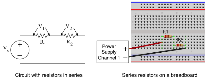
When resistors are connected in series their resistances add together. The total resistance in the circuit is then R = R1 + R2 and by Ohm's Law the current flowing in the circuit is given by

Since the same amount of current is flowing through both of the resistors, the voltage across each resistor is then

For this calculation assume that Vs has been set to 5V.
Using the values of R1 and R2 that you measured with the DMM, calculate what the voltage should be across each of the two resistors. Hint: V1 and V2 should add up to Vs = 5V.
- Question 3:
- With VS = 5V, what are the calculated voltages V1 and V2 across resistors R1 and R2?
To test the above results we have to provide the Vs power supply to the circuit.
- Make sure the power supply outputs are off (green button not lit up)
- Adjust the voltage on channel 1 of the power supply to be 5.0V.
- Plug the red and black banana plugs of the test leads with the pins on the end into channel 1 of the power supply.
- Plug the pins on the other ends of the test leads into the breadboard at the points where the positive and negative Vs voltages are to be connected to your circuit as shown above on the right.
- Turn on the power supply outputs.
- Plug the test leads with banana plugs on one end and test clips on the other into the DMM if they aren't there already.
- Set the multimeter to measure DC volts and measure the voltage drop across each resistor. One test lead should touch the resistor lead on one side of the resistor, the other touches the lead on the other side. If you make the connections backwards, your multimeter will just show a negative voltage. You're measuring the V1 and V2 voltages as shown above on the left.
As when you calculated the values using the voltage divider equation, the measured values of V1 and V2 should add up to Vs = 5V.
- Question 4:
- With VS = 5V, what are the measured voltages V1 and V2 across resistors R1 and R2?
Checkpoint: Show a CP your measurements on the DMM for the two voltages above to received the bonus points.
Switches for Inputs (Background + Lab Tasks)
A common input device for our embedded circuits is a simple pushbutton switch. The button consists of two electrical contacts, and when the button is pressed it connects them together. When the button is not pressed, the two contacts can have different voltages on them. When the button is pressed, whatever voltage is present on one contact is now on the other contact. We will use the switches as inputs to the Arduino in a way that allows the Arduino's program to sense whether the button has been pressed or not, and take different actions accordingly.
- From the parts bag in your project box get one of the small plastic buttons (any color) shown below on the left. On the bottom of the button are four pins that can be inserted into your breadboard.
- Install the button on the breadboard as shown in below on the right. To make the circuit work, the button must be oriented properly when installed on the breadboard. Note that two of the sides of the button each have two metal pins. The button must be installed on the breadboard so these two sides straddle the center channel. Two of pins should be in holes on one side of the channel, the other two should be in holes on the other side.
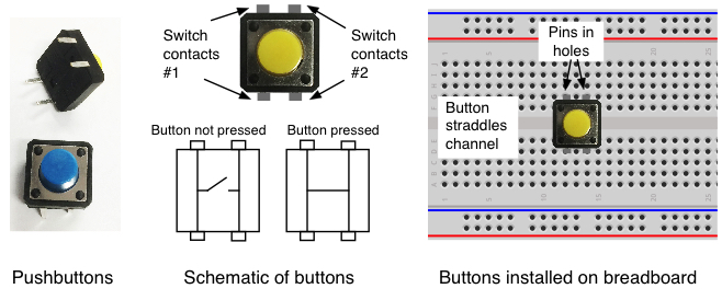
Make sure to press the button firmly into the holes of the breadboard. The black plastic body of the button should be touching the top surface of the breadboard.
- Cut off a small piece of wire and strip the insulation off both ends using your wire cutters.
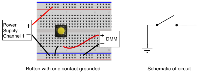
- Insert one end of the wire in one of the ground bus holes (blue bus) and the other into one of the holes below the button as shown below. Make sure the wire is inserted into the same group of holes that the pin from the button is inserted into so they will make an electrical connection.
- Connect the power supply to the breadboards with the black lead going to the ground bus on the breadboard and the red lead to the power bus as shown.
- Connect the multimeter to the breadboard in a similar fashion. The black lead from the DMM goes to the same ground bus that the power supply is attached to. The red lead goes to the other switch contact. Note that there should be one column of unused holes between the button's ground connection and the red DMM lead as shown in the figure.
- Set the DMM to measure DC Volts by pressing the "DC V" button.
- Set the power supply output for 5.0 Volts and turn the output on with the green button.
- Note: What we have wired is an INCORRECT way of wiring a button. We want to show you that while you CAN produce a clean '0' (low) voltage, you CANNOT produce a clean '1' (high) voltage.
- The meter is now measuring the voltage on one of the switch contacts. Try pressing the button and see how much the voltage changes. When the button is not pressed the voltage reading will NOT be stable. It will slowly increase. Spend a few seconds watching the voltage value "float" around. Read below to understand why.
When the switch is pressed, the output side of the switch that is connected to the DMM should show the voltage is pretty close to zero volts since the switch is connecting it to ground. However when the switch isn't pressed, the voltage can be just about anything since the switch output isn't connected to anything. It will probably be close to zero volts but may be something a bit higher (perhaps somewhere between 0 and 1.0 volts), and the value may drift up or down as you watch it. Try touching the metal part of the red lead near the switch with your finger and this may cause the measured voltage to change. This circuit isn't really doing anything useful and the reason is because when the switch is open (not pressed) the output isn't connected to anything that would cause a known non-zero voltage to appear there. In electronic circuit terminology, we would say the output is floating.
- Question 5:
- What are the voltages (or range of voltages after watching for a few seconds) on the switch output when it is not pressed and when it is pressed?
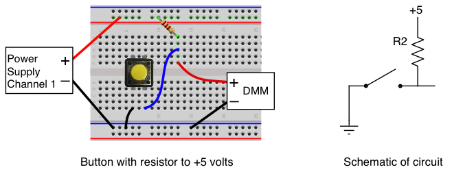
To make the switch circuit into something useful we need to change the circuit so the output isn't floating when the button is not pressed. Turn the power supply output off with green button and then make the changes shown below.
- Remove the DMM red lead from the hole below the button and move it
to some unused five hole connection block. - Using resistor "R2", the one with the middle resistance value from the three you worked with above, install it with one end in the +5V bus and the other end in connection blocks where the DMM's red lead is.
- Take a piece of wire and make a connection between the hole below the switch and the connection block where the DMM and resistor are wired.
Turn the power supply output back on and repeat the observations you did before.
- Question 6:
- With resistor R2 added to the circuit, what are the voltages on the switch output when it is not pressed and when it is pressed?
If you wired the circuit properly, the output should be very close to +5V when the button is not pressed and be very close to zero volts when it is pressed. By adding the resistor between the button output and the +5V, we've eliminated the floating problem and the output of the button now covers a much wider range of voltage between the pressed and not pressed state. The output is also now solidly fixed at the value you are reading. It won't wander up and down like it did when it was floating.
For now don't worry about why this works. We'll cover the details of why the resistor is needed in a later lecture.
Light Emitting Diodes (LEDs) (Background + Lab Tasks)
LEDs are hooked up in circuits in a similar fashion as resistors in that they both have two leads and current goes in one and out the other. However unlike a resistor the two leads are different. One is the "anode" and the other is the "cathode". Current can flow through the LED from the anode to the cathode but not the other way. When a voltage is applied across the LED causing current to flow from the anode to the cathode the LED lights up.
LEDs come in several package shapes and sizes. For this lab we are using LEDs in a 5mm round case and your parts bag should contain three of different colors (red, green and yellow). These have two leads on the bottom and the anode lead is slightly longer than the cathode. In addition there is a flat spot on one side of the plastic case to indicate the cathode. Get one of the LED from the parts bag and examine it. Make sure you can identify which lead is the anode (longer lead, round side of case) and which is the cathode (shorter lead, flat side of case).
LEDs also respond to a voltage across it differently from a resistor. Unlike a resistor where the voltage across it goes up linearly with the amount of current passing through it, an LED has the property that the voltage across the LED is always about the same (around 2.0 volts) for the typical amount of current needed to light up the LED. However, if the LED is just connected to a voltage source by itself the LED will allow as much current to pass through it as the voltage source can supply. This can result in way too much current going through the LED and may cause it to burn out. To prevent this we always use a resistor in series with the LED, as shown in the circuit on the left below, to limit the amount of current passing through the LED to a reasonable value.
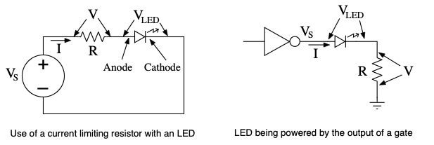
By selecting the appropriate value for the resistor the amount of current through the LED can be limited to whatever is needed. Referring to schematic above on the left, Kirchoff's Voltage Law says that
Vs = V + VLED = IR + VLED
where VLED is the voltage drop across the LED. Solving for I gives
I = (Vs - VLED)/R
This shows that we can adjust the amount of current passing through the LED by changing the value of the resistor. Note that the voltage source powering the LED does not have to be a power supply as shown in the schematic above on the left. The LED can be powered by the output of a gate as shown above on the right. This is the way we typically use LEDs with them connected to either a gate output or to an output from a microcontroller such as the Arduino.
Logic Circuits (Background + Lab Tasks)
Video Introduction - Inverters
Now that we have an input device that can signal two different states, and an output device to use as an indicator, let's use some digital logic to hook them together and make them do something.
We want to make the switch turn the LED on when the switch is pressed and off when it's not pressed. In the experiment above when the switch was pressed it produced a low voltage (logical zero), however the LED lit up when a high voltage (logical one) was present to cause current to flow through it. To make the circuit operate as desired, we need a digital circuit that causes an input of a one to produce a output of zero, and vice versa. As we will see in later classes, the action of changing a signal from high to low or low to high is known as a logical inversion.
For the inverter operation we'll use a 74HCT04 integrated circuit which in included in your parts bag. Note: It can be difficult sometimes to read the part number on the top of the integrated circuit, but one of the three IC's should say 74HCT04 on top, perhaps with some other numbers and letters there also.
The 74HCT04 contains six logical inverters that each change an input of zero to a one, and a one to a zero. The IC has 14 pins on it, numbered from 1 to 14. Use the diagram below to locate on the IC the mark or notch that identifies the location of pin 1. Once you have identified pin 1, install the 74HCT04 on your breadboard as shown so that the chip straddles the slot down the center of he board and is oriented so pin 1 is on the side of the slot closest to the blue line. Make sure the 74HCT04 is seated firmly into the holes of the breadboard otherwise its pins will not make solid contact with the breadboard connections.

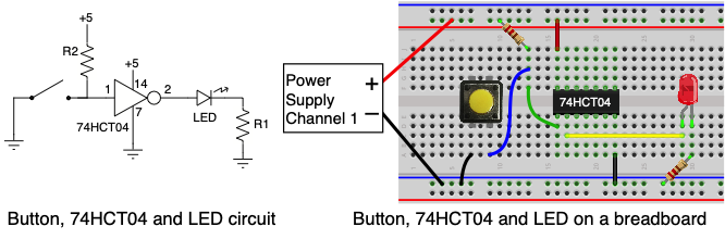
Remove the connections to the DMM and follow the schematic diagram and picture above to make the following wiring connections.
- Connect pin 14 of the 74HCT04 to the red power bus.
- Connect pin 7 of the 74HCT04 to the blue ground bus.
- Connect the input of the inverter (pin 1) to the connection block with the R2 resistor and the switch. This is the green wire in the picture above.
- Insert one lead of resistor R1 (the lowest resistance value) into a hole in an unused connection block, and the other end of the resistor R1 goes into a hole in the blue bus (Ground). This will be the LED's current limiting resistor.
- Install the LED so the cathode (shorter lead, flat side of case) is in the connection block with resistor R1, and the anode (longer lead, round side of case) is in another available connection block. Don't worry if you get it backwards. The LED is not going to burn up, it just won't light up like it should. If that happens, pull it out and try it the other way.
- Connect the output of the inverter (pin 2) to the anode of the LED (round side). This is the yellow wire in the picture above.
Turn on the power supply outputs and try pressing the button. If it's wired properly, pressing the button puts a logical zero on the inverter input, which produces a logical one on the output and that lights up the LED.
As discussed above, the value of the resistor determines how much current will flow through the LED, and therefore how bright it will be.
- Replace the the R1 resistor with R3, the resistor with the highest resistance of the three, and see if the brightness of the LED changes. Since the R3 resistor is about 5 times higher than R1, it allows much less current to flow through the LED and it should be noticeably dimmer.
Measuring Current
In the previous section you were asked to observe how changing the resistor affected the current flowing through the LED and this resulted in the brightness changing. Now we want to use the DMM to measure the current passing through the LED. We'll do this two ways, first by measuring the voltage across the resistor and using Ohm's Law to calculate the current, and then by measuring the current directly with the DMM.
First use the DMM in DC voltage mode to measure the voltage across the resistor. The diagram below shows how the meter should be connected.
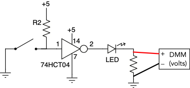
- Set the DMM to measure DC volts
- Connect the positive (red) lead from the DMM to the side of the resistor closest to the voltage source, which in this case is the output of the 74HCT04 inverter.
- Connect the negative (black) lead from the DMM to the side of the resistor closest to the ground on the bread board.
- Press the button to light up the LED and record the voltage shown on the DMM, and which resistor, R1 and R3, this was for.
- Swap the resistor you were using (either R1 or R3) for the other one and repeat the measurement.
- Question 7:
Using the values you just measured for the voltages across R1 and R3, and the values you measured previously for those resistor values, use Ohm's Law to calculate the current that was passing through the resistors in both cases.
Measuring Current with the DMM
Video Introduction - Measuring Current with the DMM
Now we'll measure the current directly with the meter rather than by measuring voltage and using Ohm's Law. Current measurement are done differently than voltage measurements since the current has to pass through the DMM to be measured. In the schematic below note how we have broken the connection between the LED and the resistor and inserted the meter in series with them so the current that passes through the LED and the resistor also has to go through the meter.
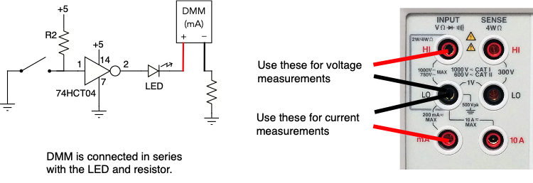
- If your DMM is still connected to the circuit for measure voltage disconnect both leads of the meter from the circuit.
- On the meter plug the red lead into the the banana jack that is marked for "mA" as shown above. The black lead should remain plugged into the "LO" jack.
- Adjust the meter to measure DC current by pressing the button marked "DC I".
- Disconnect the resistor from the LED as shown in the schematic above.
- Connect the red lead from the DMM to the LED, and the black lead to the resistor as shown.
- Press the button to light up the LED. If the connection was done properly the LED should light up and the DMM should show how much current was flowing in the circuit.
- Record the current shown on the DMM, and which resistor, R1 and R3, this was for.
- Swap the resistor you were using (either R1 or R3) for the other one and repeat the measurement.
- Question 8:
What were the values that you measured with the DMM in current mode for the current flowing through the LED for both R1 or R3? The values should be close to what you found from measuring the voltages and using Ohm's Law.
Don't Take the Circuit Apart!
The circuit you just built with the button, inverter and LED will be used again in Lab 2. Leave all the components on the breadboard and just keep it in your lab kit until the next assignment.
Whoops! It doesn't seem to be working. Now what do I do?
If a circuit you have built isn't working, then it's time to do some debugging. When a circuit doesn't work it's probably only one part that isn't functioning correctly but that makes the whole circuit not work right. When trying to debug a circuit it's necessary to isolate where the problem is by testing separate parts of the circuit to see if they work or not. Your goal is to figure out what is working and what isn't, so you can isolate the problem to a subset of the whole circuit. Here are some debugging tips.
- Use the DMM to make sure the power supply voltage is present on the breadboard and at any point that requires the power supply voltage like the power pin of all the ICs.
- Make sure the ground connections are installed to the breadboard and to any place on the circuit that should be connected to ground.
- Use the DMM to test the output of any buttons that are installed. If the pullup resistors have been installed correctly when the button is not pressed that point should be high (logical 1). When the button is pressed it should go to ground.
- If your circuit uses ICs like the 74HCT00 and 74HCT04, use the meter to confirm they are working. For example find the input voltage to an inverter and then check the output voltage. If it's working they should be opposite of each other.
- Just because you installed a wire between two points doesn't guarantee the signal is getting from one end to the other. The wire may be broken or not making good contact. Test the signal at both ends to make sure the connection is working.
- Make sure the ICs are plugged fully into the breadboard, and all the pins are in the breadboard holes. When inserting an IC it's easy to bend a pin so it's not going into the holes. If this happens and a pin is bent so badly it can't be straightened, try using one of the other gates on that IC, or get a replacement from the teaching staff.
Results
The answers to the above questions should be edited into the "Lab1_Answers.txt" file
and the file uploaded to the Vocareum web site by the due date. See the Assignments page of the class web site for a link for uploading.
Please make sure to save all the parts used in this lab in your project box. These will be needed for labs throughout the rest of the semester. We suggest also saving all the pieces of wire you cut and stripped since those will be useful in later labs.
Review Questions
Answer the following questions in your "Lab1_Answers.txt".
- Given the digital circuit you built with the button, inverter and LED, suppose as you test it the output LED is always OFF regardless of the button position. For each of the following possible explanations, write a sentence that explains why that issue would cause the LED to always be off.
- VDD was not connected to the IC chips.
- The ground connection for the button was not connected correctly.
- The LED was plugged in backwards.
- Given two resistors RLO and RHI whose resistance values are such that RLO < RHI
- If they are connected in series giving a series effective resistance of REff, which of the following is true?
- REff < RLO
- RLO < REff < RHI
- RHI < REff
- If they are connected in parallel, giving a parallel effective resistance of REff, which of the following is true?
- REff < RLO
- RLO < REff < RHI
- RHI < REff
- If they are connected in series giving a series effective resistance of REff, which of the following is true?
- True or False: Ohm's Law applies to both LEDs and resistors.