EE109 – Spring 2023: Introduction to Embedded Systems
Serial Data
The four-channel Keysight (ex-Agilent) MSO-X 3024A oscilloscopes in VHE 205 have special triggering modes that allow them to capture RS-232 serial data transfers and display them. These triggering modes should be used whenever looking at these signals rather than just using the standard edge triggering. This web page briefly describes how to setup the scopes to acquire RS-232 data and display it.
The RS-232 communication standard actually only refers to the hardware and electrical characteristics of the signals, but over the years many people also use the term to refer to the timing and format of the signals. "True RS-232" uses signals that use positive and negative voltages like −8V for a logical 1, and +8V for a logical 0. In EE109 we often instead use what people sometimes call "TTL serial" which uses the same timing and signal format at normally used with RS-232 but uses +5V for a logical 1 and 0V for a logical 0. The Keysight scopes can display TTL serial signals in the same manner as the true RS-232 ones by making a couple changes to the settings. To view TTL serial signals, follow the steps below but look for places where it says to make changes for viewing the TTL serial signals.
To view RS-232 data transfers follow the steps below. If at any time during the setup you want to make a menu disappear from the screen, press the "Back" button near the lower right corner of the screen.
- Turn on the scope and then turn on input channel 1 by pressing the button with number 1 on it in the vertical section of controls until the trace appear on the screen.
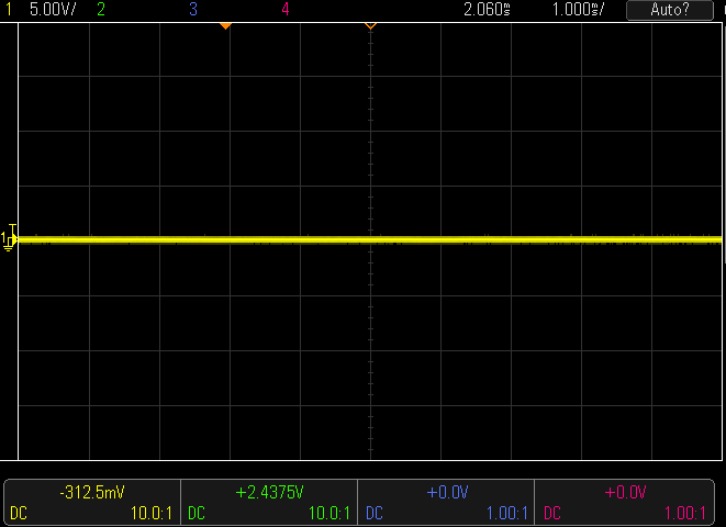
- Use the large knobs above the "1" button to adjust the input levels for the channel to 5 Volts per division. The levels for the channels are shown in the upper left part of the screen.
- Use the small knobs below channel buttons to vertically position the yellow trace in about the middle of the screen.
- Use the large knob in the horizontal section of the controls to change the horizontal sweep speed to 1ms (time/division). The sweep speed is shown in the upper right portion of the screen.
- The small knob in the right part of the horizontal section changes the horizontal position of the displayed signal. First press the knob to center the signal on the screen, and then rotate the knob to move the small orange triangle at the top of the screen over closer to the left side of the screen. When an serial signal is captured, it will be displayed with the starting point of the signal at this position.
- Connect a scope probe to channel 1 of the scope and then connect the probe tip to the source of the serial data on your breadboard. Connect the black ground lead of the probe to ground on the breadboard.
- The Keysight scopes can have two stored configurations for working with serial signals like RS-232. To setup a one for RS-232, press the "Serial" button in right portion of the screen. This brings up the Serial Decode Menu along the bottom of the screen as shown below. Press the left soft key and it should show the two Serial selections. If Serial 1 doesn’t have the box next to it filled in with a blue square, press the button again to select it.
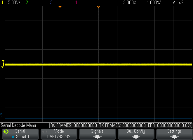
- The label for the second softkey from the left shows the current protocol selection for the bus. If it doesn’t say "UART/RS232", press the softkey below the label to bring up a vertical menu for selecting the protocol type. Using the knob with the illuminated green arrow just to the right of the screen, select the "UART/RS232" setting for Serial 1.
- Press the third softkey from the left labeled "Signals". The serial data triggering mode is designed to look at two RS-232 data streams at the same time, and one is called the Tx or transmitted data and the other is the Rx or received data. For looking at just one data stream either can be used but for this example we'll use the Rx channel. The labels above the softkeys show which scope channels are assumed to have the Rx and the Tx data connected to them. If the number below the Rx label is not 1, press that softkey and use the knob to change the channel setting to 1.
- For the Rx channel, press the "Threshold" softkey and then use the selector knob to adjust the voltage threshold.
- For TTL serial, set to around +2.5V .
- For true RS-232, the threshold should be set to something around the 0 volts since the signals go both positive and negative.
- Press the "Back" button to get back to the Serial Decode Menu and then press the "Bus Config" softkey. This brings up the screen shown below.
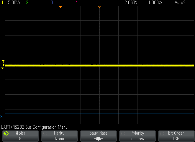
- On the Bus Configuration Menu, use the softkeys to set the RS-232 communications parameters.
- # Bits = 8
- Parity = None
- Baud rate = whatever you are using
- Polarity
- For TTL serial set polarity to "Idle high"
- For true RS-232, set polarity to "Idle low"
- Bit Order = LSB
- Press the "Back" button to get back to the Serial Decode Menu and then press the "Settings" softkey. On this screen press the "Base" softkey, and adjust its setting to "ASCII". The scope will now display the captured serial data as ASCII characters rather than as hexadecimal values.
- Press the "Trigger" button in the Trigger section of the controls to bring up the Trigger Menu.
- Press the "Trigger Type" softkey to bring up the vertical menu of triggering types, and use the selector knob to scroll down near the bottom and select "Serial 1".
- Press the "Trigger Setup" softkey to bring up the UART/RS232 Trigger Setup Menu.
- The "Trigger" softkey is used to select the RS-232 condition that will cause the scope to acquire data. For most purposes we want to trigger on the RS-232 "start bit" that indicates the beginning of the data transfer. We're using the Rx channel so if it doesn't say "Rx Start" on the label, press the softkey to bring up the "Trigger" menu and use the selector knob to set it for triggering on an "Rx Start Bit".
- Press the "Mode/Coupling" button in the Triggers section of the controls. Use the left softkey that says Mode to set the triggering mode to "Normal".
At this point the scope is configured to trigger on a RS-232 start bit. Press the "Single" button in the upper right to put the scope in a state where it will wait for the next start bit and then capture the data. Do whatever is needed on your project board to get it to generate the RS-232 transfer, and once the data has been captured it will be displayed on the screen as shown below.
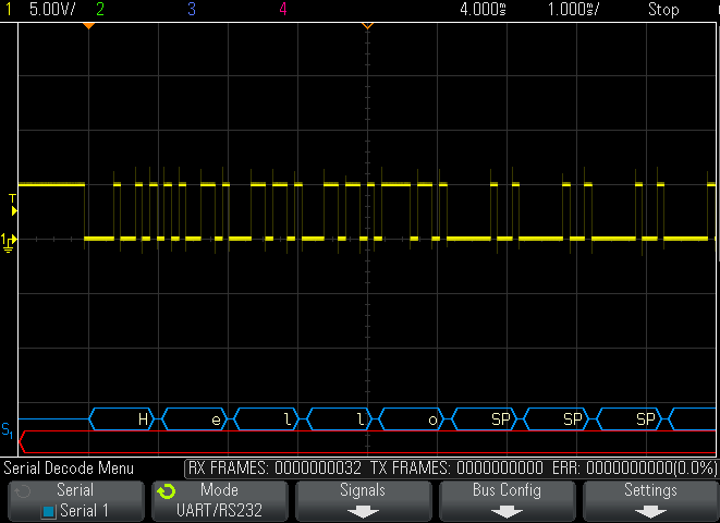
The bottom portion of the screen should show the contents of each byte in the the RS-232 transfer as an ASCII character. The space character is indicated as "SP". If you wish to see the data in hexadecimal, go back to the Settings menu and change the Base to Hex. When displayed in hex, the hex values only show the 8-bits contents, not the start or stop bits.
The captured data can be expanded or shrunk horizontally using the horizontal scale control. If you shrink the data to try to see more of it, it may not show up since the scope only stored the part that was to be displayed. In this case you will have to repeat the acquisition of the data to capture more data. The smaller knob in the horizontal section can be used to move the display left or right to see all parts of the RS-232 data.