EE109 – Spring 2023: Introduction to Embedded Systems
Lab 4
Using the LCD Display
Honor Statement
This is an individual assignment. The code you write, use for the demo and submit should be wholly your own and not produced by working in teams or using, in part or in whole, code written by someone else (found online, from a fellow student, acquaintance, etc.). You will be asked to verify this when you submit your code on Vocareum by signing your name in the honor.txt file on Vocareum. Penalties for violation include a 0 on the assignment and a potential further deduction or referral to Student Judicial Affairs.
Introduction
In this lab exercise you will attach an LCD display to the Arduino Uno and write software to display characters on it. The steps required to communicate between the microcontroller and the LCD display are typical of how most devices are interfaced to a microcontroller.
For a copy of the Lab 4 grading sheet, click here.
Background Info
The LCD Module
The LCD display used in this exercise is a monochrome, 16 character by 2 line display that uses a parallel interface. LCD displays are designed with either a serial or parallel interface, and both types have advantages and disadvantages. A serial interface transfers data one bit at a time and requires only one or two I/O lines from the microcontroller but is slower and often more expensive. A parallel interface display transfers data multiple bits at a time and can usually transfer data faster but requires multiple I/O lines from the microcontroller in order to operate.
The LCD is called an "LCD shield" since the display module is mounted on a board that plugs directly into the sockets on the Arduino Uno so it doesn't require any wires to be run between the Arduino and the LCD. Once mounted on the Arduino it uses seven of the Uno's I/O lines for data and control signals (Port D, bits 4-7 and Port B, bits 0-2).
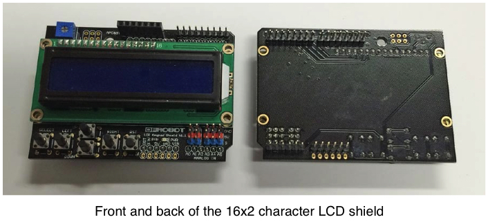
The LCD shield also has a cluster of six pushbuttons. Five of these are interfaced through a multistage voltage divider to ADC channel 0 of the Arduino. Depending on which of the five buttons is pressed, or none, one of six analog voltages appears on the ADC Channel 0 input. By using the ADC to convert the voltage to a number it's possible to easily determine if one of the five buttons was pressed. The sixth button, marked "RST" is connected to the RESET line of the Arduino and can be used to restart the program.
The LCD Interface
The parallel interface to the LCD is used to transfer data between the microcontroller and a special integrated circuit (IC) in the LCD module that controls where the dark and light spots appear on the display. The presence of this IC allows the microcontroller to display the letter 'A' by just sending the ASCII code for an 'A' (0x41) rather than having to send information about the individual dots that make up the letter on the screen. The circuit used on this module (Hitachi HD44780) is one of the most commonly used for controlling LCD modules and is designed to communicate with a microcontroller using eight data lines and three control lines. However in order to save I/O lines it can also communicate in a 4-bit mode that sends an eight bit byte in two 4-bit "nibbles", first the most significant four bits, then the least significant four bits. The four bit mode is used with this LCD shield.
In addition to the four data lines, the controller IC has three control lines: RS (Register Select), RW (Read/Write) and E (Enable). On the LCD shield the designers have eliminated the the RW line so data can only be written to the shield. A third control line can be used to control the LCD backlight. The result of all this is that the shield can be used with just seven I/O lines, four for data and three for control signals.
- Command/data bits 4 through 7 (Arduino I/O pins D4-D7 = PORTD, bits PD4-PD7)
- These lines carry four bits of the command or data bytes that are sent to the LCD. Most operations require sending a full byte so transfers have to be done in two steps.
- Register select (Arduino I/O pin D8 = PORTB, bit PB0)
- Set to 1 to write to the data register. Clear to 0 to write to the command register.
- Enable (Arduino I/O pin D9 = PORTB, bit PB1)
- All writes to the data or command registers are done by making the Enable line do a 0→1→0 transition.
- Backlight control (Arduino I/O pin D10 = PORTB, bit PB2)
- This control line is not used in any of our lab assignments. It's important that the PB2 bit NOT be enabled as an output or this can cause the backlight to go off and the characters on the LCD will be impossible to read. Bit 2 in the DDRB register should never be set to a one.
Command and Data Registers
Inside the controller IC on the LCD module are two 8-bit registers, the command register and the data register. The Register Select control line is used to determine which register the microcontroller transfers data to.
When the microcontroller wants the LCD to perform certain operations it writes the necessary 8-bit command code into the command register to initiate the operation. Typical commands include clearing the display, moving the cursor to some location, turning the display on or off, etc.
The data register is where the program writes the ASCII character codes for the characters that it wants to have displayed on the LCD. When a character is written to the data register it will appear on the display at the location that the cursor was at, and then cursor will move to the right one position. Writing a string of characters to the data register (one after the other) has the effect of making the string appear on a line of the display with the cursor positioned after the last character in the string.
Command and Data Transfers
Transferring commands and data to the LCD involves a number of steps all involving setting or clearing bits in the six I/O port bits (PORTD[7:4] (data), PORTB[1] (E) and PORTB[0] (RS)) that are connected to the six interface lines described above. The LCD shield does all its data transfer in the 4-bit interface mode. In some cases only 4 bits have to be transferred, in others a full 8-bit must be transferred.
Important: After an entire 8-bit data or command byte is sent a short delay is needed. A 2msec delay should be sufficient. For 8-bit transfers, it is not necessary to delay between transferring the upper and lower parts of the byte, but there should be a delay after the second part of the transfer.
Task 1: Test the LCD Shield
Install the LCD shield on the top of the Arduino Uno. Make sure that you are lining up the pins and connectors properly before trying to push them together. Two of the male headers on the shield are the same size as the mating connectors on the Uno and these go into the D0-D7 and A0-A5 connectors. The other two male headers have fewer pins than the connectors they are plugged into. Take care to make sure that all the pins are going into the correct openings before applying pressure to push the two boards together. The LCD shield should be seated all the way into the sockets. There should be little or no gap between the sockets on the Arduino and the bottom of the black connectors on the LCD that the pins stick out of. If you have problems mounting the shield on the Uno ask one of the instructors for help.
Create a lab4 folder in your ee109 folder. From the class web site download the file lab4.zip, extract the files and put them in the lab4 folder. You should have these six files for Lab 4:
- Makefile
- This is a modification of the normal Makefile to allow testing of the LCD shield
- test.hex
- The binary test program for the LCD shield
- lab4.c
- Template file containing functions declarations to get you started
- lcd.h
- Function prototypes to be included in your lab4.c
- lcd.c
- Actual implementation of LCD functions. You will need to complete the lcd_init() and write the code for the
lcd_writedata,lcd_writecommandandlcd_writenibble()functions. - Lab4_Answers.txt
- Edit this file to answer the review questions at the end of this web page, and upload to Vocareum.
Make the usual changes to the PROGRAMMER line at the top of the Makefile to make it work on your computer. Attach your Arduino+LCD to your computer and enter the command "make test" to download the data from the test.hex file to the Uno. Once the download is complete the LCD should show two lines of text as shown below.

If nothing shows up on the screen or it shows a lot of white boxes, try changing the display contrast by using your screwdriver to adjust the blue control in the upper left corner of the display. If you can't get the test program to work, ask one of the instructors for help. Don't try working on the rest of the lab assignment until the test program is working.
Task 2: Write the LCD Functions
This lab exercise is a good example of how programs can be structured so the complexities of one part are hidden from other parts of the program. As much as possible the details of how the LCD module works should be handled by only a small portion of the code. Most of the program should not have to deal with knowing which I/O port bits are being used, setting the control bits, dealing with delays, etc., for each character it wants to display. To put a character on the display, the program just has to call a function that has the character to be displayed as its argument. All the details about how that character gets transferred to the LCD should be isolated in another part of the program. Doing this has an additional advantage that the LCD could be changed for a model with a different interface, and only the small number of routines that deal directly with the interface will have to be changed.
Our LCD software will be designed with the three layers described below:
Low level function(s):
The low level function, lcd_writenibble will handle the changing of the bits in the I/O ports connected to LCD. Most of the "bit fiddling" will be done in this function. The primary task will be sending a 4-bit "nibble" to the LCD and creating the Enable signal transition from 0 to 1 back to 0. You will need to complete this function in this lab (in the file lcd.c).
Mid level functions:
The mid level functions lcd_writedata and lcd_writecommand deal with sending data and commands to the LCD by making use of the low level functions. These functions transfer one byte each time they are called. You will need to complete these functions in this lab (in the file lcd.c)
Top level functions:
The top layer has a small number of simple functions (initialize LCD, position the cursor, write a string of characters) that make use of the mid level functions. The main part of the program only calls the functions in the top layer. The functions for positioning the cursor and writing strings are provided. You'll only add lines to lcd_init() to initialize the I/O ports the LCD uses.
The lcd.c file has the functions listed below, either complete or to be written. Start with
that file and add code to implement the functions.
Low Level Functions
The low level function "lcd_writenibble" transfers a four bit value from the 8-bit (unsigned char) argument to the LCD. All transfers of data and commands depend on this function to do the actual transfer. Assume RS has already been set to 0 or 1 OUTSIDE of this function. Don't set it inside this function.
void lcd_writenibble(unsigned char lcdbits)
{
    /* Send four bits of the byte "lcdbits" to the LCD */
}
All transfers of data and commands depend on this function to do the actual transfer. Data is only transferred to the LCD when the E (Enable) signals makes a 0→1→0 transition, and the lcd_writenibble routine is the only function that changes the state of the E line.
The argument to lcd_writenibble is an 8-bit "unsigned char" variable, but only four of these bits will be transferred to the LCD. Note that it is very important that "lcd_writenibble" and the functions that will be calling it agree as to which 4-bits of its 8-bit argument it will send to the LCD (i.e. place on PD[7:4]). It is likely easiest to copy the upper 4-bits of the lcdbits argument to PORTD[7:4] so that's what we will using.
Once the four bits are copied to PORTD bits 4 through 7, then the E signal (PB1) has to make a 0→1→0 transition to cause the LCD to read the 4 bits. Data is only transferred to the LCD when the E (Enable) signals makes a 0→1→0 transition, and the lcd_writenibble routine is the only function that changes the state of the E line.
Try to write this function now.
Important: Your lcd_writenibble routine must only change the bits in registers B and D that need to be changed in order to affect the transfer. Don't just copy a full byte into a register if you only need to modify a few bits. Any bits that are not part of the transfer should not be changed. Reference your Unit 6 slides on Copying bits to see how to do this. You will lose points if you modify any other bits not associated with the LCD.
Mid Level Functions
Two mid level functions are used to send a byte to the command register and the data register.
void lcd_writecommand(unsigned char cmd)
{
    /* Send the 8-bit byte "cmd" to the LCD command register */
}

void lcd_writedata(unsigned char dat)
{
    /* Send the 8-bit byte "dat" to the LCD data register */
}
These routines must set the register select line to the correct state for a command (RS=0) or data (RS=1) transfer, and then make two calls to the low level "lcd_writenibble" function. Recall that we decided that lcd_writenibble would always transfer the upper 4-bits of its argument. So to transfer 8-bits we first send the upper four bits of the byte (normal call to "lcd_writenibble"), and then send the lower 4 bits. However to send the lower 4-bits we will need to move the lower 4-bits of the data we want to transfer in our current function into the upper 4-bit area of the argument we pass to "lcd_writenibble" (since "lcd_writenibble" expects the 4-bits it is supposed to transfer to be in that upper 4-bit area). An appropriate shift operator >> or << can be used to do this as you pass the argument. The picture below shows this concept:
![]()
After an 8-bit transfer is complete, the function should delay for about 2msec to let the operation finish.
Note: We could have written "lcd_writenibble" to use the lower 4-bits of its argument and then changed the mid-level functions appropriately. There is no real advantage to doing it one way or the other. The only important thing is that the three functions agree on which to use.
Locate the two routines in lcd.c and add the code necessary to make them work as described above.
- Configure the RS (Register Select) line to determine the destination of the data transfer. RS=0 indicates a command transfer. RS=1 indicates a data transfer.
- Call the lcd_writenibble procedure to write the upper four bits of data (bits 7-4)
- Move the lower 4-bits of the desired information to the upper 4-bit area
- Call the lcd_writenibble procedure to now write these bits to the LCD
- Wait 2 msec
Only the code for step 1 above differs between the two functions. The code for steps 2 through 5 should be the same in both functions.
Top Level Functions
The top level routines are to initialize the LCD and to write strings of characters starting at specified locations. These routines should make use of the functions defined in the mid level (and if necessary the lower level) of the program. Task such as moving the cursor to a given location on the screen, writing a string of ASCII characters, etc. are common top-level tasks and the routines that do this lcd_moveto and lcd_stringout are provided for you.
Unfortunately you can't just start sending character data to the LCD and have it appear. The module has to have a few initialization steps performed before it will accept data and display it. These are handled by the lcd_init and most of the code for these operations has been provided already in lcd.c file. However before any initialization commands can be sent to the LCD, the Arduino's I/O ports must be configured properly to work with the LCD. The LCD uses Port B, bits 0 through 2 for control signals, and uses Port D, bits 4 through 7 for data signals. You will need to do the following steps.
- In
lcd.cfind the functionlcd_init. - At the top of this function, add the necessary code to configure Port B, bits 0 and 1 for output. Port B bit 2 should be left as an input so it won't cause the LCD backlight to go off.
- Add the necessary code to configure Port D, bits 4 through 7 for output.
Important: The code you add to lcd_init should only configure the DDR bits for the Port bits being used by the LCD. Don't modify any other DDR bits. The rest of the LCD initialization requires several data transfers to it, most followed by delays of specific lengths. The code for these steps have been provided for you already in the lcd_init function and should not be changed.
After the above steps are done the display is ready to accept data to display. If you now write data to the data register it should appear on the screen starting in the upper left position.
The templates for the following two functions for moving the cursor and writing a string of characters are also in the lcd.c file but we will not be writing these in this week's lab assignment.
void lcd_moveto(unsigned char row, unsigned char col)
{
    /* Move the cursor to the row (0 to 1) and column (0 to 15) specified */
}

void lcd_stringout(char *str)
{
    /* Write the string pointed to by "str" at the current position */
}
Displaying Characters
The LCD display uses the ASCII character codes to determine which characters to display. Once the LCD has been initialized as shown above, any byte written into the data register will result in the character with that ASCII code being displayed on the LCD and the cursor that indicates where the next character will go is advanced one position to the right. For example if the bytes with values 0x55, 0x53, 0x43 are written to the data register one after the other, the character ``USC'' will appear on the screen. Note: if you write more characters than will fit on a line, it doesn't automatically wrap to the next line.
The Makefile
Before starting to make changes to the lab4.c file we need to change the Makefile. The source code for the Lab 4 assignment is not in just one file as with Lab 3. It's in two files, lab4.c and lcd.c, so you must modify the OBJECTS line in the Makefile to indicate this.
OBJECTS = lab4.o lcd.o
From now on whenever you type "make", it will compile both lab4.c and lcd.c (if needed) and link them together to form the executable program.
Task 3: Check the Enable Signal
The LCD requires that the Enable or E signal be at least 230ns long. To check that your code has satisfied this requirement do the following.
- Disconnect the LCD panel from the Arduino by gently pulling it out of the sockets. Have one of the instructors help you with this if you are concerned about breaking the LCD.
- Important: In lab4.c add a line to call your lcd_init() function. It should be called somewhere between the start of the main() routine and the while(1) loop. If you don't call this function, your DDR bits won't be set properly and you won't get a proper E signal.
- In the while(1) loop of the main routine in lab4.c, insert code to call the lcd_writedata function.
while (1) {
    lcd_writedata(0);
}
This will cause the lcd_writedata routine to be called repeatedly and each time it will generate two E pulses close together followed by a 2ms delay.
- Compile the code by typing "make". If you made the proper changes to the Makefile as described above you should see that it compiled both the lab4.c file and the lcd.c file.
- Download it to the Arduino. Remember to use "make flash" to download your program. The "make test" is only used to download the test program in the test.hex file.
- Turn on the oscilloscope and connect one of the probes to channel 1.
- Set the triggering to trigger on channel 1, a rising edge, and a trigger level of about 2 volts.
- Using a short piece of wire, hook the probe to the Port B, bit 1 output (D9 on the Arduino). Don't forget to also connect the probe's ground wire to ground on the Arduino.
- Adjust the scope setting to allow you to measure how long the E pulse is in the 1 state. Since the
lcd_writedatahas a 2ms delay after sending the data, most of the time the signal will be at the zero level. The two E pulses will be very narrow spikes that occur every 2ms. If the scope is triggering properly on the signal you should be able to adjust the horizontal timing to get a clear view of the width of the E pulse.
If the E pulse is not at least 230ns long you can extend the pulse by adding additional instructions to your lcd_writenibble function. For example the code below sets Port B, bit 1 to a one, and then sets it to a one a second time before it's cleared to a zero.
PORTB |= (1 << PB1);        // Set E to 1
PORTB |= (1 << PB1);        // Make E longer
PORTB &= ~(1 << PB1);       // Set E to 0
The second line has no effect on the PB1 output signal since it is already in the 1 state, but it extends the time the signal is high before the third line clears it to a zero.
If necessary, add one or more of these extra instructions to your code and observe the results on the scope. Add enough delay that the E signal is in the 1 state for at least 230ns.
Checkpoint: Show a CP your "E" signal of the correct width on the oscilloscope to receive the bonus points.
Task 4: Build a One Digit Up/Down Counter
Put your LCD back on the Arduino for the rest of the lab assignment.
Now that you have the LCD routines written and have confirmed that the E signals meets specifications, we want to build a circuit with three buttons labeled "Up", "Down" and "Pause" that does the following.
- The LCD display continuously shows a counting value that changes every 0.5 secs.
- The count value goes from 0 to 9 when counting up and 9 to 0 when counting down.
- When counting up, the count value should start over at 0 after 9 is reached (… 7, 8, 9, 0, 1, 2, …). When counting down, the count value should start over at 9 after 0 is reached (… 2, 1, 0, 9, 8, 7, …).
- Pressing the "Up" button or "Down" button changes the count direction accordingly. Pressing the "Pause" button stops the counting at the current count value until either "Up" or "Down" is pressed. When a button is pressed to change the count direction, it should start counting in that direction from the current count value (don't start over at zero.)
- Once a button has been pressed to set the direction, the button does not have to be held down. The counter should continue to count in that direction until the another button is pressed to reverse the direction or pause the counting.
To see a short video demonstrating the operation of this lab, click here.
The Circuit
From your lab box you will need
- Three pushbuttons of different colors.
- The package of male-female jumper wires. These are needed to make connections between the LCD, which has pins poking up, and the breadboard that has holes for the wires to go into.
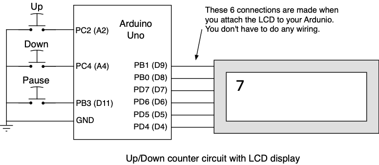
Install the push buttons on your breadboard and connect them as shown in the schematic below. The schematic shows both the internal ATmega328P names of the port bits (e.g. PC2) and the corresponding name marked on the Arduino board (A2). The switch inputs are on Arduino bits A2, A4 and D11 which are connected to the microcontroller's I/O bits PC2, PC4 and PB3.
Finding the I/O Ports
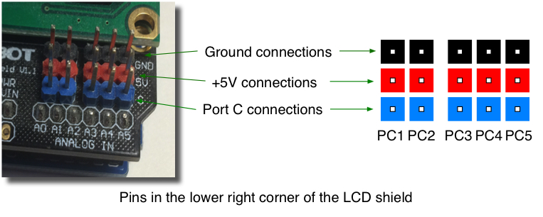
Once the LCD is installed on top of the Arduino, you no longer have access to the black connectors on the Arduino in order to make connections to the I/O Ports. To remedy this, the available I/O port pins (those that are not used in communicating with the LCD) are bought up to the top of the LCD shield. Some are available as pins that stick up from the base of the LCD circuit board and you can make connections to these pins using the jumpers. Other are available from the black connectors on the LCD that you can stick wires into. For this lab you need to connect to two of the pins of Port C, PC2 and PC4. The Port C pins can be found on the blue pins at the lower right corner of the LCD as shown below. Please note that there is no connection for PC0 even though there is a "A0" marking on the PC board near the connector. PC0 is used internally by the LCD and as a result there is no pin available to connect to it.
The connection for Port B, bit 3 (PB3) is made in a similar way to one of the pins sticking up in the upper right corner of the LCD. Port B, pin 3 is referred to as the "D11" bit on the Arduino so look for the pin labeled "D11" along edge of the LCD board as shown below.

All other Arduino I/O port bit (B0, B1, B2, C0, D4, D5, D6 and D7) are used by the LCD and are not available for connections on the LCD.
A State Machine
To build our up/down counter we will implement it using the principles of a state machine. A state machine saves information about previous inputs by storing that information as the machine's "state". The state information can then be referenced by the machine as it operates to determine what to output next, and perhaps, which state to transition to next.
The state diagram for our counter is shown below. There are three state (UP, DOWN and PAUSE), and the transitions from one state to another are caused by the pressing of one of the buttons.
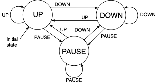
The initial state for the counter is the UP state as shown above.
The lab4.c file contains a declaration of the three states with the statement
enum states { UP, DOWN, PAUSE };
The constants "UP", "DOWN" and "PAUSE" can now be used to indicate which state the machine is in. To store this value you should define a state variable that stores the state (UP, DOWN or PAUSE) that counter is in. For example,
my_counter_state = UP;
Whenever the program senses that a button has been pressed it can change the setting of the state variable. Note that pressing a button only changes the setting of the up/down/pause state variable. Pressing a button doesn't change the count, it simply changes the state variable to tell the program which way to count, up or down, or to pause. Every time the program needs to change the count, it checks the state variable to determine whether to make the count value higher or lower or remain the same.
Please use the structure of nested if statements shown in the State Machines Unit in your lecture notes and discussed in class. Don't just try to "wing-it" or make your own state machine approach. Instead, use the suggested structure.
Displaying the Count Value
The LCD displays ASCII characters. If you use lcd_writedata to send it the value of your count variable (e.g. 2) you will get garbage on the screen since 2 is not the ASCII code for the digit 2. To display the count value you have to convert it to an ASCII character code.
If you look at an ASCII chart it shows that the ASCII code for the digits '0' through '9' are 0x30 through 0x39. So to display a digit, just add 0x30 to it and call lcd_writedata with this value as the argument.
For example:
unsigned char cnt = 5;
lcd_writedata(cnt + 0x30); // '5' will appear
lcd_writedata(cnt + '0');  // '5' will also appear because '0'=0x30
If you just keep calling lcd_writedata each time the count changes, the characters will just march across the LCD: "0123456789012345". We need to move the cursor to the same location before each time lcd_writedata is called so the count values stay in the same place. The simplest way to do that is to send a command to the LCD that makes it move the cursor to the "home" postion in first column of the first row. To move the curso the "home" postion, call the lcd_writecommand function with an argument of 2.
lcd_writecommand(2); // Move to row 0, column 0
Once the cursor has been moved to the upper left, the next character sent to it by calling lcd_writedata will simply overwrite the previous count value shown at that location.
Alternatively, you can do a "clear screen" operation that clears all the character positions on the LCD and also moves the cursor to the first position on the first row. To clear the screen, call the lcd_writecommand function with an argument of 1. After the screen has been cleared, the program can call lcd_writedata to display the count character in the first position on row 1.
The Program
Your program should start by doing the following operations.
- Call the
lcd_initfuntion to initialize the ports necessary to control the LCD and send the initialization commands to the LCD. - Configure the two Port C input bits and the Port B bit to have their pull-up resistors enabled.
- Declare a char variable to contain the current count value and initialize it to be zero.
- Declare a char variable to serve as the state variable for storing the counting direction. The counting direction state variable should always be set to one of the
enumconstants described above: UP, DOWN or PAUSE. - Initialize the count direction state variable to start off in the up direction.
The main loop of the program is an infinite loop that does the following four actions:
- Examine the three button inputs to see if any are being pressed, and if so, set the state variable to the appropriate value. If no button is pressed, the state doesn't change.
- Determine the next value to be displayed based on the current count value and the state variable, and update your variable storing the current count value accordingly.
- Display the current count value on the LCD. This will require doing a
lcd_writecommandoperation to either "home" the cursor or clear the screen, and then writing the count value withlcd_writedata.
Important: Your program should only write a number to the screen if it has changed, so when in the PAUSE state your code should not keep writing the same number to the screen each time around the loop. - Wait one half of a second. As in Lab 3, delays can be implemented with the _delay_ms function.
Note 1: When direction is changed it should count from whatever number we are currently at and not restart at zero or nine.
Note 2: A common "poor" approach is to check if the direction is UP or DOWN and then enter a while loop to count up or down for 10 values. But this would mean we can't look for new button presses (direction changes). Instead, you should only need the main while(1) loop and no other loops. Only increment or decrement the count once per iteration of the main while loop and let the loop repeat to perform the next increment or decrement.
A Problem
Once you have the counter working try an experiment. Wait until the displayed digit changes and then quickly press the button to change the counting direction but only hold it down for very short time. The counting direction probably won't change. Now try it again but this time hold the button down until after the next count change and then let it up. Has the count direction changed? Take a look at your code and try to determine why this is happening. Why does a quick press of the button sometimes not work but a longer one does?
Think about how we could modify the software to still have the counter change every half second, but be responsive to button presses at any time in the cycle and for any length. Try to implement your ideas and see if you can make the buttons always change the counter direction regardless of when they are pressed or for how long.
One hint: Suppose we wanted to do something once a week, we can't just do it once and then go to sleep for a week and wake up 7 days later (well, most of us can't). We have other things to do as well. Thus we wake up at a finer granularity (once per day). If we kept a counter (starting at 0), we could increment it every day we wake up and then only when the counter reaches 7 would we know it has been a week and we can do our weekly task. Then we can set our counter back to 0 and repeat the process of incrementing the count each day we wake up. In this way I can still do weekly tasks (when the count reaches 7) but also do more frequent, daily tasks since I wake up every day.
This approach can be extended if we have several tasks that each need to be done at a different interval period (e.g. something every 100 ms, another thing every 250 ms, and a third every 400 ms) we can find a smaller granularity (say 50 ms) to increment a counter (or three separate counters) and only perform the 3 tasks when the count reaches the appropriate threshold (e.g. 2 for 100 ms, 5 for 250 ms, and 8 for 400 ms...The modulo operator can be helpful if you want to use only 1 counter).
Results
When your program is running you should be able to
- Confirm that the count values are being displayed correctly on the LCD.
- Show that you can change the direction of the counting using the buttons.
- Confirm that in both count directions the sequence wraps around properly when it reaches the maximum or minimum count value.
- Show that you can pause the count when counting in either direction, and the up/down buttons resume the counting.
- Show that the counter responds to short button presses to change the direction.
Try to organize your code to use good style and indentation. Examine your solution for repetitive code that can be "factored" and replaced with a function, or other similar enhancements to make the code readable and modular. Points may be deducted for failure to do so. Once you have the assignment working demonstrate it to one of the instructors.
The answers to the review questions below should be edited into the Lab4_Answers.txt file. The Lab4_Answers.txt file and all source code (lab4.c, lcd.c, lcd.h and Makefile) must be uploaded to the Vocareum web site by the due date. See the Assignments page of the class web site for a link for uploading.
Please make sure to save all the parts used in this lab in your project box. These will be needed for labs throughout the rest of the semester. We suggest also saving all the pieces of wire you cut and stripped since those will be useful in later labs.
Review Questions
Answer the following questions and submit them in a separate text file ("Lab4_Answers.txt") along with your source code.
- Normally we only read the bits in the PIN register, but a close reading of the ATmega328P datasheet reveals that writing a 1 to PIN register bit has the effect of inverting the bit in the corresponding PORT register. For example, if you write a 1 to PINC, bit 3, it will invert bit 3 in the PORTC register. Based on this information, Billy Bruin has decided that he now knows an easy way to "toggle" the E bit (flipping it to its opposite value) to generate the E pulse in the
lcd_writenibble()function by using this code.PINB |= (1 << PB1); // Toggle E bit from 0 to 1 PORTB |= (1 << PB1); // Delay to make the E pulse longer PINB |= (1 << PB1); // Toggle E bit from 1 to 0
Note: PINB |= (1 << PB1); is equivalent to PINB = PINB | (1 << PB1);
Tammy Trojan has also read the datasheeet and found that when reading the PIN register, if a bit in the group is configured as input, the the voltage coming in the PIN is returned, but if a bit is configured as output, the corresponding PORT bit value is returned. From this she concludes that Billy's method can cause problems when used and recommends using this code to generate the E pulse.
PINB = (1 << PB1);     // Toggle E bit from 0 to 1
PORTB |= (1 << PB1);   // Delay to make the E pulse longer
PINB = (1 << PB1);     // Toggle E bit from 1 to 0
Tammy says that in this lab assignment with the PAUSE button on PB3, Billy Bruin's code will cause the PAUSE button to stop working. Can you explain why this would happen?
- Suppose we need to perform 3 concurrent tasks intermittently: Task A every 20 ms, Task B every 15 ms, and Task C every 40 ms. What delay should be used on each iteration of the main loop?